

Ferrite Core Selection Guide for Switching Power Supply Design
Ferrite Core Selection Guide for Switching Power Supply Design
Selecting the wrong ferrite core for a switching power supply is one of the most expensive mistakes in power electronics design. A core that’s too small saturates and overheats. One that’s oversized wastes board space and budget. Getting it right requires understanding how core geometry, material grade, and operating conditions interact.
This guide walks through the core selection process step-by-step — from defining your operating parameters to choosing the right core type and size from the TOMITA catalog.
Step 1: Define Your Operating Parameters
Before looking at any core catalog, nail down these basics:
**Switching Frequency (fsw)**: The single most important parameter. It determines which material grade you need and constrains your achievable power density. Lower frequencies (50–100 kHz) allow larger cores with better thermal margins. Higher frequencies (200–500 kHz) enable smaller cores but demand lower-loss materials.
**Input and Output Voltage**: These define your turns ratios and influence flux density swing (ΔB). A wide input voltage range (say, 85–265 VAC) requires a core that can handle the resulting wide flux swing without saturating.
**Output Power and Efficiency Target**: Your power level drives core size. Efficiency targets affect how much self-heating you’ll need to dissipate — and whether a smaller core with a better material grade can handle the thermal load.
**Operating Temperature Range**: The maximum ambient temperature plus self-heating must stay below the Curie temperature of your chosen material. For enclosed designs with limited airflow, derate core performance by 15–20%.
Step 2: Calculate the Required Ae·Aw Product
The core’s ability to handle power is determined by two key parameters:
**Ae** (effective cross-sectional area) — determines magnetic flux density for a given applied voltage and frequency. Larger Ae = lower flux density = less core loss.
**Aw** (window area) — determines how much copper you can wind. More copper = lower resistive losses = higher efficiency.
The product Ae·Aw correlates directly with power handling capability. Larger power levels require larger Ae·Aw products.
TOMITA’s catalog provides Ae, le (effective magnetic path length), Ve (effective core volume), and Aw for each core type — use these to calculate whether a given core can support your design.
Step 3: Estimate Flux Density Swing (ΔB)
For a given core geometry and operating frequency, the flux density swing is determined by applied voltage and duty cycle:
ΔB = (V·t_on) / (N·Ae)
Where:
– V = applied voltage
– t_on = switch on-time per cycle
– N = number of turns
– Ae = core cross-sectional area
The goal: keep ΔB well below the saturation flux density (Bsat) of your chosen material, typically 390–490 mT for Mn-Zn ferrites at room temperature. A practical design targets ΔB of 150–250 mT at maximum load — providing headroom for temperature rise and component variation.
If your calculation shows ΔB approaching 300 mT or higher, you need either a larger core or a higher Ae.
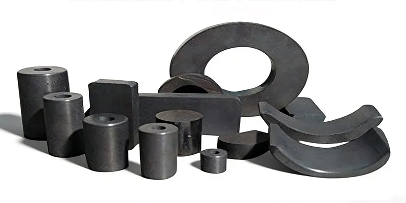
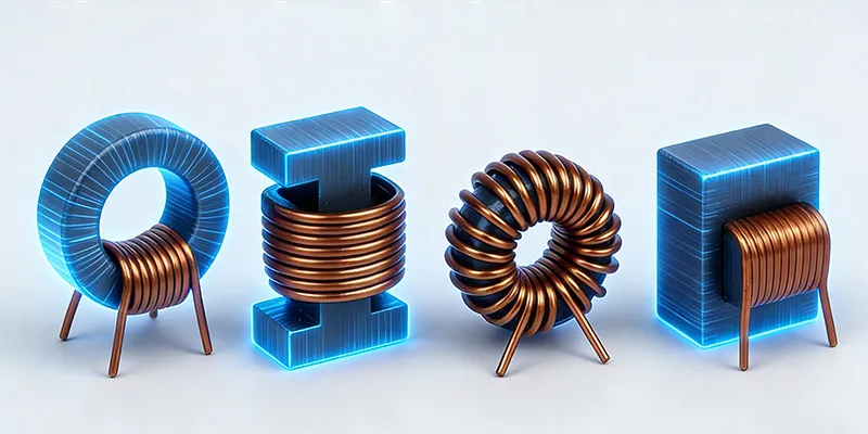
Step 4: Match Core Type to Application
Different core geometries serve different functions in switching power supplies.
EER Type (EER-28, EER-35, EER-40)
The EER geometry offers a good balance of Ae and winding window. Its circular center post provides uniform winding geometry and consistent magnetic path. EER cores are the workhorse for isolated forward converters and flyback transformers up to about 500W.
Best for: Forward converters, flyback transformers, push-pull converters.
ETD Type (ETD-34, ETD-39, ETD-44)
ETD (Eclipse Toroidal Derivative) cores feature a larger window area than EER types for the same Ae — meaning more copper fit and lower resistive losses. The geometry also enables lower total height, which matters in flat power supply designs.
Best for: Half-bridge and full-bridge LLC resonant converters, high-current applications.
PQ Type (PQ-2620, PQ-3230, PQ-3535)
The PQ series is optimized for power inductors — not transformers. Its geometry maximizes Ae while minimizing winding window (since power inductors typically need only a few turns of heavy gauge wire). This gives maximum inductance in minimum footprint.
Best for: Energy storage inductors, output filters, boost and SEPIC converters.
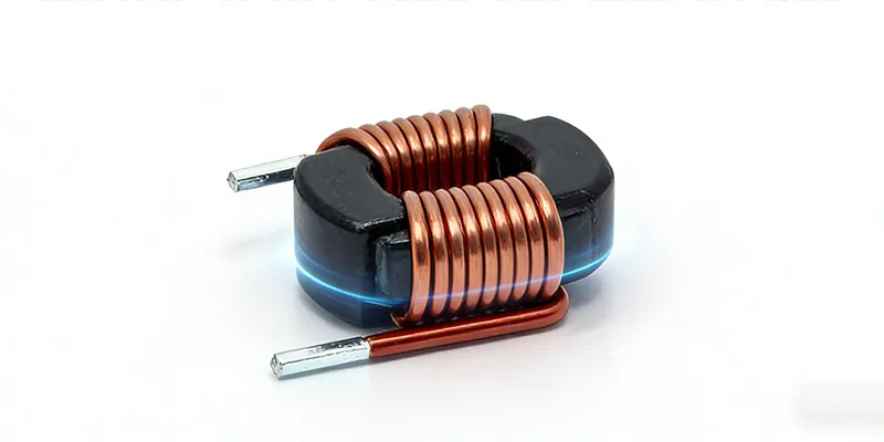
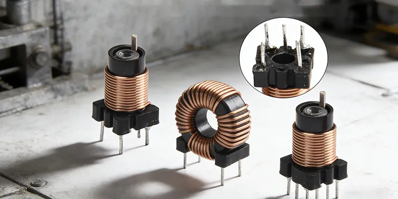
Toroidal Cores
Toroids offer excellent magnetic coupling and minimal EMI radiation — the flux is largely self-contained. However, they require manual winding or specialized equipment, and thermal dissipation can be challenging in high-power designs.
Best for: EMI suppression, high-frequency filters, low-power applications where EMI is critical.
Step 5: Choose Your Material Grade
Once you’ve identified the right geometry, select the material grade based on your switching frequency:
| Frequency Range | TOMITA Grade | Comparable TDK | Typical Application |
|---|---|---|---|
| 20–100 kHz | 2G8 | PC44 / N67 | Standard SMPS, PFC |
| 100–300 kHz | 2G8A | PC47 | High-efficiency converters |
| 300–500 kHz | 6G8 | Ferrite 7A | High-frequency designs |
| 500 kHz–5 MHz | 4A3 (Ni-Zn) | B1 / N9 | RF and very high frequency |
For most consumer electronics power supplies (100–250 kHz), TOMITA 2G8 or 2G8A is the practical choice. Both offer low losses and good temperature stability at these frequencies.
Step 6: Validate Thermally
The final check: will the core run within acceptable temperature limits?
Core loss (Pcv) at your operating frequency, flux density, and temperature generates heat. TOMITA’s catalog provides Pcv curves showing loss per unit volume at different frequencies, flux densities, and temperatures.
Calculate total core loss in your design, then estimate the temperature rise using the thermal resistance of your mounting method. As a rule of thumb, natural convection without thermal interface material typically gives 30–50°C/W thermal resistance for open-frame designs.
If calculated temperature rise exceeds 60°C above ambient, consider:
– Increasing core size
– Reducing flux density (more turns, smaller wire — tradeoff)
– Improving thermal interface to a heatsink or chassis
– Switching to a lower-loss material grade
Quick Reference: Core Selection Summary
| Application | Core Type | TOMITA Grade | Notes |
|---|---|---|---|
| Flyback Transformer (<200w )< td> | EER-28/35 | 2G8 | Most common low-power topology |
| Forward Converter | EER-35/40 | 2G8 | Simple, efficient at moderate power |
| Half-Bridge LLC | ETD-39/44 | 2G8A | Resonant, high efficiency |
| Output Inductor | PQ-2620/3230 | 2G8 | Energy storage, high current |
| EMI Common Mode | Toroid / DNW | 2H5 | High permeability for max inductance |