

Understanding Ferrite Core Loss and Thermal Management
Core losses in ferrite components are invisible during normal operation — until they are not. A ferrite core running hotter than expected is almost always losing more energy than the design predicted. Left unchecked, thermal runaway can destroy a transformer or inductor in minutes. Understanding and managing core loss is therefore fundamental to reliable power supply design.
What Drives Core Loss in Ferrites
Ferrite core losses have three components, often referred to as the Steinmetz equation:
Pcore = Cf × f^x × B^x + Ce × f² × B² × (t/δ)² + Cp × f³ × B³ × d²
Where the three terms represent hysteresis loss, eddy current loss, and residual loss respectively. In practice, hysteresis loss dominates at lower frequencies and flux densities, while eddy current loss grows rapidly with frequency — at hundreds of kilohertz it can account for the majority of total loss.
The Frequency and Flux Density Dependence
Both hysteresis and eddy current losses scale with the switching frequency and operating flux density. This is why increasing the switching frequency of a power supply — a common strategy for reducing transformer size — does not linearly reduce total losses. As frequency goes up, core losses increase faster than the magnetic material can shrink in size.
Modern ferrite materials from manufacturers like Ferroxcube, TDK, and Magnetics are characterized using the generalized Steinmetz parameters (α, β, and k), which allow loss prediction across a wide frequency and flux density range. Always use these parameters rather than simplified "loss at 100 kHz" figures for accurate thermal modeling.
Thermal Runaway: The Critical Failure Mode
Ferrite core loss increases with temperature — but so does resistivity, which paradoxically reduces eddy current loss. The net effect is a complex temperature dependence that does not self-limit. If the rate of heat generation exceeds the rate of heat dissipation, temperature rises, losses change, and the core can enter a thermal runaway condition.
The Curie temperature marks the point where ferrite loses its magnetic properties entirely — typically 200–250°C for MnZn ferrites. Below this, permeability drops progressively as temperature increases. A transformer designed to operate at 100°C with a given inductance will progressively lose inductance as it heats toward 150°C, potentially causing circuit instability before outright failure.
Thermal Management Strategies
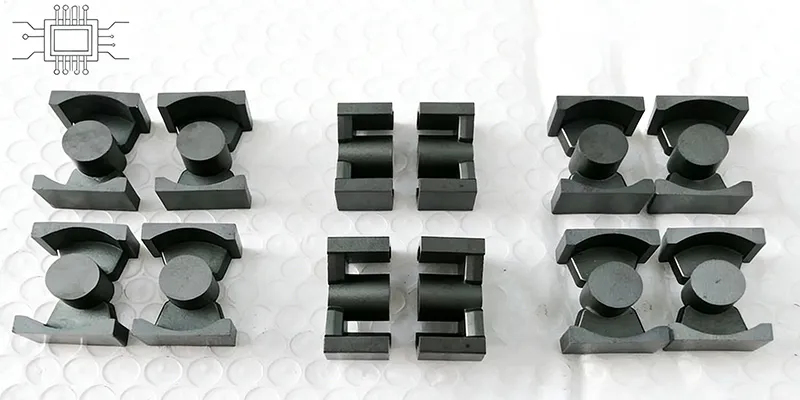
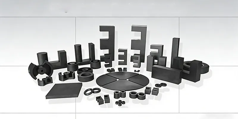
Heat sinking: For larger E-core or ETD transformers, thermal compound and mechanical fastening to a metal chassis or dedicated heatsink can dramatically improve heat removal.
Core selection: Low-loss material grades (sometimes designated with "L" or "LP" prefixes) sacrifice some permeability to achieve substantially lower core loss at operating frequencies. The cost premium often pays back in thermal headroom.
Winding design: Proximity effect losses in the windings contribute to the total loss budget and generate heat adjacent to the core. Using Litz wire or multi-strand construction reduces proximity effect in high-frequency, high-current transformers.
Forced air cooling: For power supplies exceeding 100W, forced-air cooling is often necessary to maintain acceptable temperature rise. The relationship between airflow (CFM) and temperature rise is nonlinear — doubling airflow does not halve the temperature rise.
Measuring and Validating Thermal Performance
Design calculations estimate steady-state temperature based on total losses and thermal resistance. Direct measurement using a thermocouple embedded in the core (where feasible) or an infrared thermometer on the surface provides the most reliable validation. Target a temperature rise of 40°C or less for components with long life expectations; 60°C is acceptable for shorter-lifetime consumer applications.
Conclusion
Core loss and thermal management are inseparable in power supply design. The losses define the heat load; the thermal environment determines the resulting temperature. Successful designs balance switching frequency against core material losses, provide adequate thermal paths, and maintain sufficient margin to survive worst-case operating conditions without thermal runaway.
Shenzhen Gaorunxin Technology Co., Ltd