

Why Floating Connectors Exist: Solving Vibration & Stress in PCB-to-PCB Connections
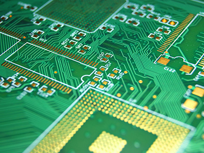
If you have ever opened an industrial control cabinet or taken a close look inside an automotive electronics module, you have almost certainly come across a board-to-board connector — a component that electrically links two PCBs together to carry signals and power. But have you ever stopped to wonder: what challenges does this seemingly straightforward connection face in real-world operating conditions?
1. The Challenge of High-Density Interconnects
As electronic products become increasingly complex, the density of PCB-to-PCB interconnections continues to grow. The higher the interconnect density, the more critical the reliability requirements become. Real-world operating environments are rarely forgiving. In automotive, industrial control, and aerospace applications, board-to-board connectors face vibration and mechanical stress from multiple directions every day. The sources of these forces are varied: complex, harsh working environments such as motor operation in automotive and industrial applications; consumer appliances like washing machines, dishwashers, and blenders generating ongoing vibration; and manufacturing tolerances and PCB warpage during assembly and operation.
2. The Cost of Rigid Resistance
When confronted with vibration and pressure, standard connectors typically respond with brute force: optimized mechanical structures, enhanced locking mechanisms, stronger materials. These approaches provide some improvement but fail to address the root cause. The reason is fundamental: standard connector pins are soldered directly to the PCB. Over time, prolonged stress and repeated mechanical movement eventually leads to deformation of the contact mechanical structure, degradation of electrical performance such as contact resistance, surface oxidation or poor contact at the contact points, and solder joint fractures causing complete connection failure.
3. The Root Cause: No Shock Absorption Buffer
From a physics perspective, the fundamental reason for these problems is the absence of any buffering mechanism between the connector and the PCB. Imagine two rigid blocks colliding head-on — all the energy concentrates at the contact surface, causing damage. But introduce an elastic layer between them, and the force is gradually absorbed and distributed, dramatically reducing damage at the interface. This is precisely the design philosophy behind floating connectors.
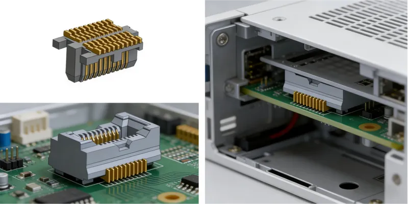
4. The Solution Takes Shape
Recognizing the inherent limitations of the rigid resistance approach, engineers began asking a different question: could we build a connector that, while retaining all the capabilities of a standard connector, also allows short-range displacement in one or more directions? The answer was yes — and this is the origin of the floating connector. A floating connector adds a floating structure on top of the standard connector foundation. This floating mechanism enables the connector to allow a degree of relative motion between mating components, absorb vibration and pressure-induced stress through elastic elements such as springs, and maintain stable contact and solder joint integrity even under adverse conditions.
5. From Component Reliability to System Reliability
The arrival of floating connectors elevated board-to-board connection reliability to an entirely new level. Their value goes beyond simply protecting the connector from damage. More importantly, they allow the entire electronic system to maintain stable electrical performance and mechanical integrity under vibration, misalignment, and deformation — conditions that standard connectors cannot handle effectively. This uplift in system-level reliability is invaluable for industries with the highest dependability requirements: premium industrial machinery, automotive electronics, medical devices, and beyond.
Conclusion
From rigid resistance to resilient engagement, the floating connector represents a significant evolutionary step in electronic interconnect technology — not a revolutionary invention, but a precise and intelligent engineering refinement built on an existing foundation.
Shenzhen Gaorunxin Technology Co., Ltd