

CRG25T135BKR3S CR Micro 1350V 25A IGBT TO-247
- Product Details
- Download
- 1350 V / 25 A continuous collector current, TO-247
- VCE(sat) 1.95 V
- Eoff 0.95 mJ per turn-off
- Trench FS-RC III technology
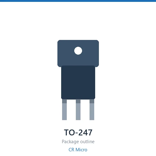
The CR Micro CRG25T135BKR3S is a 1350 V 25 A IGBT in a TO-247 package. Its saturation voltage is 1.95 V; turn-off loss is 0.95 mJ per pulse; the anti-parallel diode drops 2.7 V. The die is built on Trench FS-RC III technology.
Key Specifications
| Collector-Emitter Voltage (VCES) | 1350 V |
| Continuous Collector Current (IC) | 25 A |
| Collector-Emitter Saturation (VCE(sat)) | 1.95 V |
| Gate-Emitter Voltage (VGE) | 5.6 V |
| Turn-off Loss (Eoff) | 0.95 mJ |
| Diode Forward Voltage (VF) | 2.7 V |
| Technology | Trench FS-RC III |
| Package | TO-247 |
Same-Rating Selection Table
| Part Number | VCES | IC | VCE(sat) | Eoff | VF | Technology | Package |
|---|---|---|---|---|---|---|---|
| CRG25T135AKR5H | 1350V | 25A | 1.65V | 1.36 | 1.7V | Trench FS-RC Ⅴ | TO-247 |
| CRG25T135BKR3S | 1350V | 25A | 1.95V | 0.95 | 2.7V | Trench FS-RC III | TO-247 |
| CRG30T135AKR5H | 1350V | 30A | 1.6V | 1.28 | 1.7V | Trench FS-RC Ⅴ | TO-247 |
3 part numbers share the same 1350 / TO-247 rating — sorted by current.
Process Technology
Trench FS-RC III refers to a trench-gate field-stop structure. Field-stop layers let the wafer be thinned while keeping the blocking voltage, which cuts both saturation voltage and turn-off loss. The roman numeral is the generation: later generations trade conduction loss for switching speed.
Applications
Solar inverters, three-phase motor drives, UPS, and railway auxiliary converters.
Selection Notes
- VCE(sat) is quoted at a specific collector current and gate voltage. Re-check the datasheet curve at your actual operating current and junction temperature.
- Eoff trades directly against VCE(sat). Faster technology generations give lower Eoff at equal saturation, which is why a newer generation can run at a higher switching frequency.
- Check the short-circuit withstand time before using the part in a drive with a hard fault path.
- Confirm whether the anti-parallel diode is co-packaged or separate — the VF figure above refers to the internal diode where one is present.
Common Questions
What is the blocking voltage of the CRG25T135BKR3S?
VCES is 1350 V, with a continuous collector current of 25 A.
What is the saturation voltage of the CRG25T135BKR3S?
VCE(sat) is 1.95 V at the rated current and gate voltage stated in the datasheet.
How much switching loss does the CRG25T135BKR3S have?
Turn-off loss Eoff is 0.95 mJ per pulse under the test conditions in the datasheet. Switching loss scales with bus voltage and current, so recalculate for your operating point.
What technology does the CRG25T135BKR3S use?
Trench FS-RC III. Field-stop trench structures raise the electric field in the drift region while keeping the wafer thin, which lowers both VCE(sat) and Eoff against a planar IGBT.
What package does the CRG25T135BKR3S come in?
TO-247. Check the datasheet mechanical drawing for lead spacing and thermal pad dimensions before laying out the footprint.
How do I choose between the 3 part numbers in this rating group?
All 3 share the same voltage and package class. Sort by on-resistance first, then check gate charge: the lowest Rds(on) part is not automatically the best choice if the stage switches at high frequency. The table above lists them in ascending Rds(on) order.
Shenzhen Gaorunxin Technology Co., Ltd
Online message
Shenzhen Gaorunxin Technology Co., Ltd