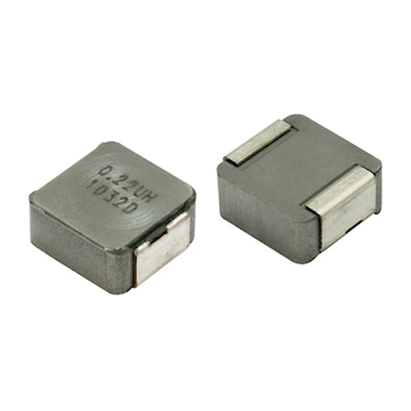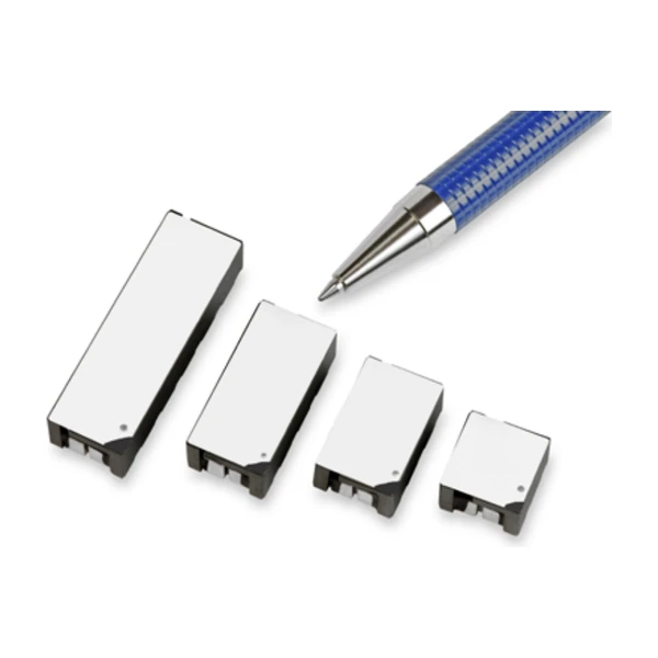
Eaton CL1208-3-100TR-R 3-Phase Multi-Phase Power Inductor, 100 nH per phase
- Product Details
- Download
Eaton CL1208-3-100TR-R 3-Phase Multi-Phase Power Inductor, 100 nH per phase
Electrical Specifications
| Parameter | Value |
|---|---|
| Orderable part number | CL1208-3-100TR-R |
| Number of phases | 3 |
| Rated inductance per phase | 100 nH ±20% |
| Open circuit inductance (OCL) | 400 nH typical / 360 nH minimum |
| Full load inductance (FLL) | 320 nH minimum |
| DC resistance (DCR) | 0.45 mOhm |
| Rated current per phase | 15 A |
| Peak current per phase | 56 A |
| Package | CL1208 footprint (see drawing) |
| Packaging | TR - tape and reel |
| RoHS | Compliant (-R suffix) |
What the Numbers Mean
A multi-phase inductor splits one input into several smaller rails so that each phase carries a fraction of the total current. The point is copper loss: total loss goes as I²R, so dividing the current across 3 phases cuts the resistive loss by roughly the square of the phase count, and lets the magnetics run at a lower flux density.
DCR 0.45 mOhm at 20 °C is the number that sets efficiency. At 15 A per phase the winding loss is 0.1 W per phase; add the core loss and the phase count to get the total inductor loss in the converter.
Where This Series Fits
CL1208 是 100 nH 多相电感,2 / 3 / 4 / 6 相,DCR 低到 0.45 mOhm。
- Typical use: 高电流多相 VRM、GPU 供电.
- 低 DCR 是这个系列的核心卖点:损耗低,效率高。代价是对电流纹波和相间平衡设计要求更高。
- Data sheet 4314; test conditions 1 MHz / 0.1 Vrms, +25 °C unless stated.
Isat marks where the part leaves its inductive region. At 15 A the inductance has already dropped well below its open-circuit value, so a design that runs close to that point trades ripple control for headroom. 3 phases is the common configuration for a mid-power VRM. The phase count is set by the converter, not by the inductor - what matters here is that this part is the 3-phase variant with the matching pinout and DCR.
Frequently Asked Questions
How do the phases connect?
The datasheet gives the pin numbering for each phase pair - (3-4)(5-6) and so on - and the layout has to keep each phase current loop tight.
What does the phase count mean?
The number of independent windings sharing the same footprint. More phases means lower current per phase, lower copper loss and better ripple cancellation.
Which inductance should I use?
The rated inductance per phase, not the OCL. OCL is measured at zero bias; FLL is what the part has at rated current and it is the number the ripple calculation needs.
Design note: use the full-load inductance and the hot-case
DCR for the loss budget, and check the layout keeps each phase current loop closed.
Mechanical Dimensions

Dimensional drawing and recommended PCB pad layout from the Eaton data sheet. Tolerances and pad dimensions are as printed on the drawing; check the outline against your layout before release.
Shenzhen Gaorunxin Technology Co., Ltd
Online message
Shenzhen Gaorunxin Technology Co., Ltd