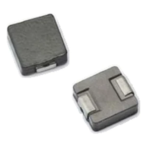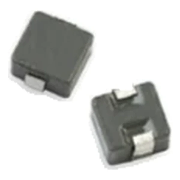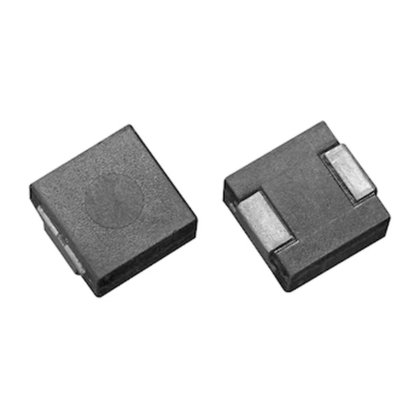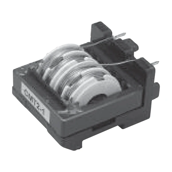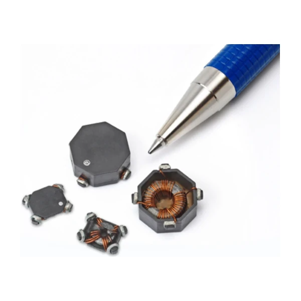
Eaton CMS2-8-R Surface-Mount Common-Mode Choke 360 uH
- Product Details
- Download
Eaton CMS2-8-R Surface-Mount Common-Mode Choke 360 uH
Electrical Specifications
| Parameter | Value |
|---|---|
| Orderable part number | CMS2-8-R |
| Open circuit inductance (OCL) | 360 uH minimum, (1-2) & (4-3) |
| I rms (max) | 1.35 A |
| DCR typical @ 20 °C (1-2) | 0.084 ohm |
| DCR typical @ 20 °C (4-3) | 0.084 ohm |
| Leakage inductance typ | 2.6 uH |
| Interwinding capacitance typ | 3.9 pF |
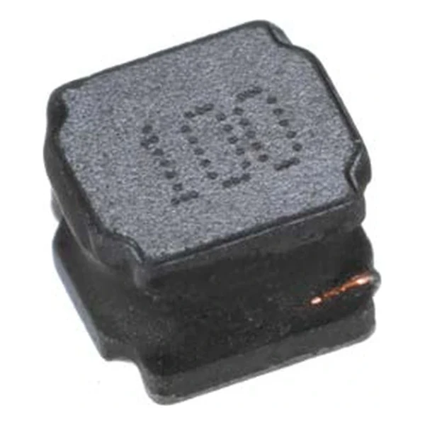
| Package | CMS series, surface mount |
| Operating temperature | 160 °C maximum |
| RoHS | Compliant (-R suffix) |
What the Numbers Mean
The impedance figure is measured across the winding pair, which is exactly the common-mode path. That is why these parts are picked by impedance at the noise frequency rather than by inductance.
Impedance rolls off with frequency and with bias, so the value on the data sheet is a starting point rather than a guarantee. Model the network, then measure. 360 uH is a high-inductance part with a correspondingly low 1.35 A Irms. The trade is deliberate - you give up current capability to get attenuation down low in the band where the noise actually lives.
Series Positioning
CMS 是贴片共模电感,CMS1 / CMS2 / CMS3 三个尺寸系列,4.5 uH 到 1310 uH。
- Typical use: 开关电源输出滤波、DC-DC 共模抑制、EMI 整改.
- CMS 的 OCL 是在 (1-2) 与 (4-3) 两组绕组上测的最小值,实际应用中两根线都要接对绕组。
- Data sheet 4313.
Irms 1.35 A is the thermal limit - a 40 °C temperature rise at 85 °C ambient. With 0.084 ohm of DCR the winding loss at that current is 0.15 W. CMS2 is the mid-size CMS footprint
Frequently Asked Questions
Why are there two DCR values?
The CMS series specifies each winding separately, measured between (1-2) and between (4-3).
Does it affect my signal?
Only through DCR and the small amount of leakage inductance. The differential signal is not filtered by design.
Is this part RoHS compliant?
Yes - the -R suffix denotes the RoHS build.
Design note: pick the choke by impedance at the noise
frequency, then confirm DCR and rated current against the signal or the rail.
Mechanical Dimensions

Dimensional drawing and recommended PCB pad layout from the Eaton data sheet. Tolerances and pad dimensions are as printed on the drawing; check the outline against your layout before release.
Shenzhen Gaorunxin Technology Co., Ltd
Online message
Shenzhen Gaorunxin Technology Co., Ltd