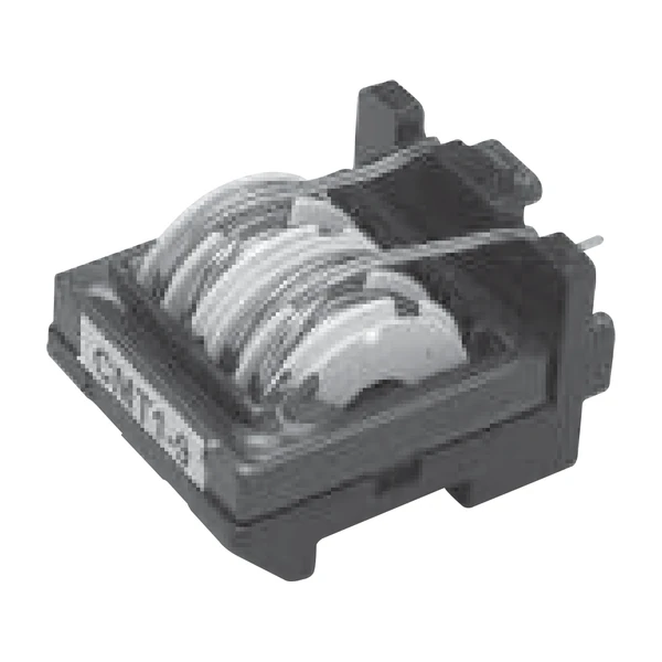
Eaton CMT1-10-R Through-Hole Common Mode Inductor
- Product Details
- Download
Eaton CMT1-10-R Through-Hole Common Mode Inductor
Ratings at a Glance
| Parameter | Value |
|---|---|
| Orderable part number | CMT1-10-R |
| Open circuit inductance (1-2), minimum | 0.94 mH |
| Open circuit inductance (4-3), minimum | 0.94 mH |
| Irms, maximum | 6.05 A |
| DCR typical @ 20 °C (1-2) | 18 mOhm |
| DCR typical @ 20 °C (4-3) | 18 mOhm |
| Mounting | Through-hole, 4 pins |
| Flammability | UL94V-0 |
| Operating temperature | -40 °C to +125 °C |
| RoHS | Compliant (-R suffix) |
The Figures Explained
Off-line supplies need a choke that will take the full AC line current without saturating, and still present a high impedance to the noise that tries to leave through the mains lead. That is the CMT.
The rated current is the RMS line current at the stated temperature rise, and the inductance is what remains under that current. A common-mode choke does not see differential DC, so saturation is not the usual failure mode here - heating is.
The two windings are measured separately, (1-2) and (4-3), because a mismatch between them turns common-mode noise into differential noise - which the X-cap then has to absorb.
Series Positioning
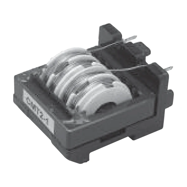
CMT is a through-hole common-mode choke for the AC input of an off-line supply, with attenuation up to 68 dB and inductance from 0.53 mH to 66 mH. It sits ahead of the bridge and stops switching noise from travelling back down the mains lead.
- Typical applications: Off-line power supplies, EMI filters, AC input of switching regulators, DC-DC converters, computer/TV/audio equipment.
- Eaton marked this series discontinued effective 1 March 2016 or while inventory lasts - treat it as a service part for existing designs, not a new-design choice.
- Data sheet 4312.
Sizing It Into a Design
0.94 mH is at the low-inductance end of what this series covers. Moving up in inductance costs DCR and saturation current; moving down buys both, at the price of ripple.
The loss budget is the whole story with a power inductor: core loss grows with frequency and flux swing, copper loss grows with current, and the two meet at a different point for every inductance in the series.
Frequently Asked Questions
What is the current rating based on?
The RMS line current at the rated temperature rise. Inrush and fault current are separate questions and are not covered by that number.
Why is there a separate OCL for each winding?
The two windings are measured separately, (1-2) and (4-3). A mismatch between them means an asymmetry in the differential impedance, so both are specified.
Can I use it on a DC line?
Only if the DC current is well below the rated value - DC biases the core and eats the inductance. Common-mode chokes are specified for AC line current in opposing directions.
Design note: rated for RMS line current, not inrush. The choke sits upstream of the bridge and downstream of the fuse - size the fuse first.
Mechanical Dimensions

Dimensional drawing and recommended PCB pad layout from the Eaton data sheet. Tolerances and pad dimensions are as printed on the drawing; check the outline against your layout before release.
Shenzhen Gaorunxin Technology Co., Ltd
Online message
Shenzhen Gaorunxin Technology Co., Ltd