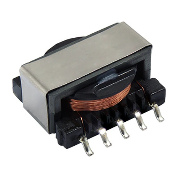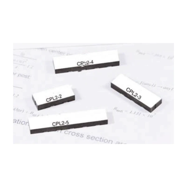
Eaton CPL2-5-50TR-R 5-Phase Coupled Inductor, 50 nH/phase
- Product Details
- Download
Eaton CPL2-5-50TR-R 5-Phase Coupled Inductor, 50 nH/phase
Electrical Specifications
| Parameter | Value |
|---|---|
| Orderable part number | CPL2-5-50TR-R |
| Number of phases | 5 |
| Rated inductance per phase | 50 nH/phase |
| DCR nominal @ 25 °C | 0.28 mOhm |
| Rated current per phase | 50 A |
| Peak current per phase | 80 A |
| OCL, per pin pair | 400 nH typical / 380 nH minimum |
| Magnetising inductance @ 5 Adc | 300 nH |
| Frequency range | up to 2 MHz |
| Mounting | Surface mount |
| Operating temperature | -40 °C to +125 °C |
| RoHS | Compliant (-R suffix) |
What the Numbers Mean
Coupling is the whole point of this family. Fifty nanohenries per phase, wound on a shared core, so that the ripple from one phase subtracts from its neighbours instead of adding. The result is a converter that can run at a lower switching frequency for the same output ripple.
The arithmetic is the usual one for coupled windings: parallel gives L/4 with 2x the current capability, series gives 4L with half. DCR follows the same rule - parallel halves the resistance, series doubles it.
The per-phase DCR is what sets the conduction loss, and the coupling is what sets the ripple. Neither number alone tells you whether the part will work in a given controller.
Where This Series Fits
CPL2 is the low-core-loss 50 nH multiphase coupled inductor: same coupling idea as CPL, revised core for efficiency, rated to 50 A per phase with an 80 A peak.
- Typical applications: High-current multiphase VRMs, Volterra and Maxim VPR controllers, point-of-load.
- DCR is quoted at ±10% here rather than the ±20% of the CPL family - the tolerance is tighter, the loss budget is not automatically better.
- Data sheet 4357.
Sizing and Layout Notes
50 nH per phase is at the design point the controller expects of what this series covers. Moving up in inductance costs DCR and saturation current; moving down buys both, at the price of ripple.
Thermal design is not optional here. The rated current assumes a 40 °C rise with the part in free air on a stated pad; inside a closed box, on a thin board, next to a hot IC, that assumption is gone.
Frequently Asked Questions
Why is the rated inductance given per phase?
Because the windings are separate phases sharing a core. The per-phase value is what sets each phase current ripple.
Can I use it with any multiphase controller?
No. Eaton specifies these families for Volterra or Maxim VPR devices, and the coupling is part of the reference design. Check the controller before you substitute.
Why is the rated inductance given per phase?
Because the windings are separate phases sharing a core. The per-phase value is what sets each phase current ripple.
Design note: use the per-phase rated inductance, not the OCL, and confirm the controller is the one the family was characterised with.
Mechanical Dimensions

Dimensional drawing and recommended PCB pad layout from the Eaton data sheet. Tolerances and pad dimensions are as printed on the drawing; check the outline against your layout before release.
Shenzhen Gaorunxin Technology Co., Ltd
Online message
Shenzhen Gaorunxin Technology Co., Ltd