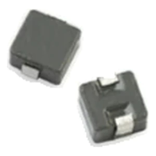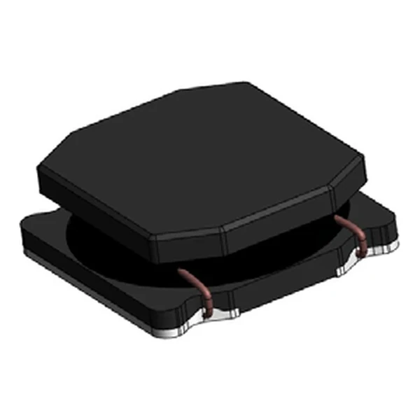
Eaton CPLA-2-50TR-R Multi-Phase Power Inductor 2 Phases
- Product Details
- Download
Eaton CPLA-2-50TR-R Multi-Phase Power Inductor 2 Phases
Ratings at a Glance
| Parameter | Value |
|---|---|
| Orderable part number | CPLA-2-50TR-R |
| Number of phases | 2 |
| Rated inductance per phase | 50 nH/phase |
| DCR nominal @ 25 °C | 0.5 mOhm |
| DCR maximum @ 25 °C | 0.6 mOhm |
| Rated current per phase | 40 A |
| OCL, per pin pair | 365 nH typical / 365 nH minimum |
| Magnetising inductance @ 5 Adc | 300 nH |
| Frequency range | up to 2 MHz |
| Mounting | Surface mount |
| Operating temperature | -40 °C to +125 °C |
| RoHS | Compliant (-R suffix) |
How to Read These Ratings
A multiphase coupled inductor shares one core between the phases, so the phase currents see a mutual inductance as well as their own. With the right phase relationship the ripple partially cancels, and the output capacitor sees less AC current than the sum of the phases would suggest.
Series mode is often mistaken for a way to get more current. It is the opposite - four times the inductance, half the saturation current, twice the DCR. Use it when you need inductance, not when you need amps.
The per-phase DCR is what sets the conduction loss, and the coupling is what sets the ripple. Neither number alone tells you whether the part will work in a given controller.
Positioning in the Range
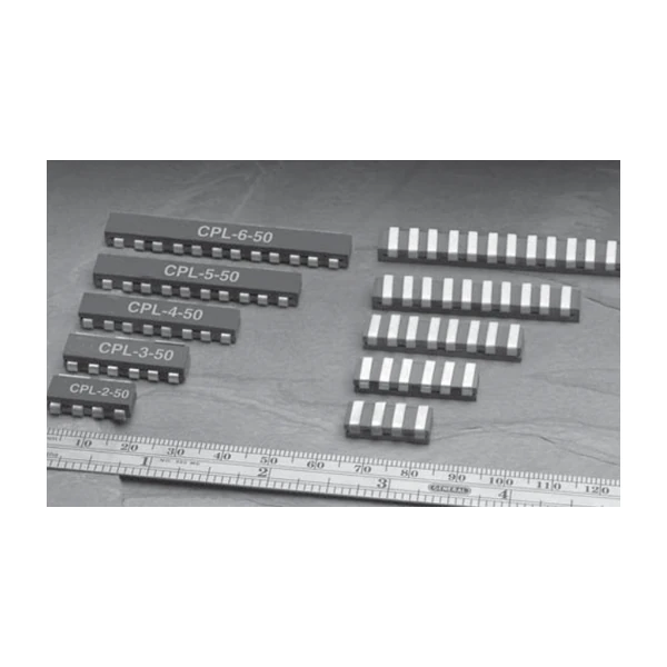
CPLA is the acoustic-noise-damped version of the 50 nH CPL. Same electrical behaviour, different construction, so the magnetostriction that makes a coupled inductor sing at the switching frequency is suppressed.
- Typical applications: Noise-sensitive multiphase VRMs, Vcore rails in equipment with acoustic limits.
- CPLA is not electrically interchangeable with CPL for every controller - the dampening changes the mechanical build; confirm with the reference design.
- Data sheet 4362.
Sizing and Layout Notes
50 nH per phase sits at the design point the controller expects of the range, and the trade at that point is explicit: 0.5 mOhm of DCR against - A of saturation headroom.
Thermal design is not optional here. The rated current assumes a 40 °C rise with the part in free air on a stated pad; inside a closed box, on a thin board, next to a hot IC, that assumption is gone.
Frequently Asked Questions
What current does the rating refer to?
Rated current per phase. The total the converter can deliver is that multiplied by the number of phases, subject to the thermal design of the board.
What current does the rating refer to?
Rated current per phase. The total the converter can deliver is that multiplied by the number of phases, subject to the thermal design of the board.
Why is the rated inductance given per phase?
Because the windings are separate phases sharing a core. The per-phase value is what sets each phase current ripple.
Design note: use the per-phase rated inductance, not the OCL, and confirm the controller is the one the family was characterised with.
Mechanical Dimensions

Dimensional drawing and recommended PCB pad layout from the Eaton data sheet. Tolerances and pad dimensions are as printed on the drawing; check the outline against your layout before release.
Shenzhen Gaorunxin Technology Co., Ltd
Online message
Shenzhen Gaorunxin Technology Co., Ltd