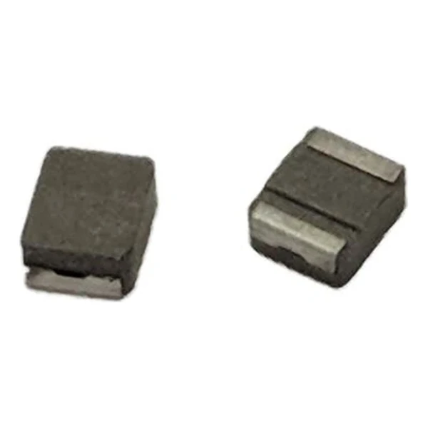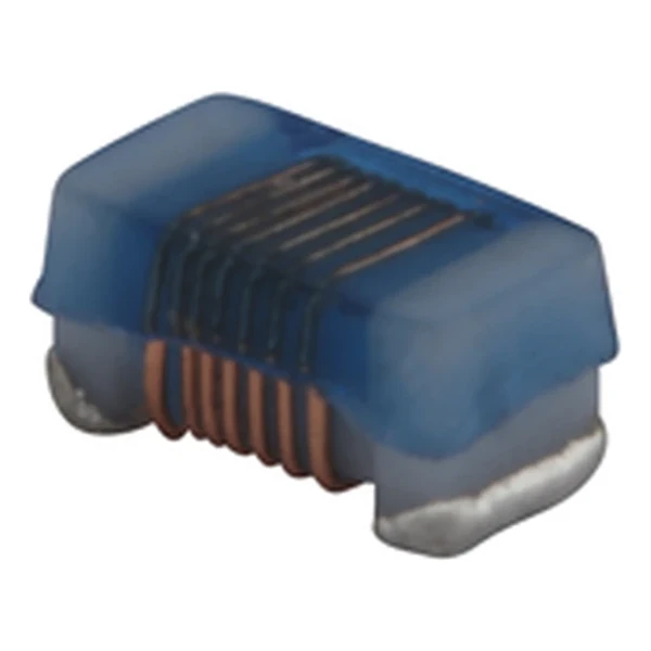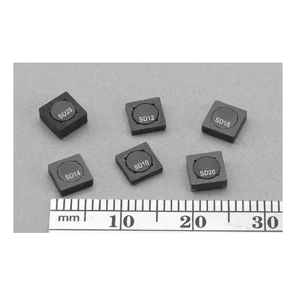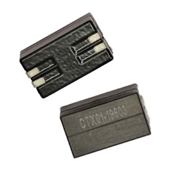
Eaton CTX01-19603-R Multiphase Coupled Inductor 375 nH
- Product Details
- Download
Eaton CTX01-19603-R Multiphase Coupled Inductor 375 nH
Specification Table
| Parameter | Value |
|---|---|
| Orderable part number | CTX01-19603-R |
| Open circuit inductance (OCL), 0 Adc | 375 nH |
| Full load inductance (FLL), minimum | 349 nH |
| Irms | 16 A |
| Isat | 52 A |
| DCR typical @ 20 °C | 1.15 mOhm |
| Mounting | Surface mount |
| Operating temperature | -40 °C to +125 °C |
| RoHS | Compliant (-R suffix) |
What the Numbers Mean
This is a coupled inductor built for a specific multiphase controller family. The winding ratio and the coupling are matched to the controller, so the part is chosen by the reference design rather than by inductance alone.
The data sheet gives OCL and FLL separately because the core is biased in use. Select on FLL for steady-state ripple, on OCL to identify the part, and on the isolation rating for anything that crosses a boundary.
Coupling is only useful inside the controller it was designed for. Outside that loop the mutual inductance can add to the ripple instead of cancelling it.
What This Family Is For
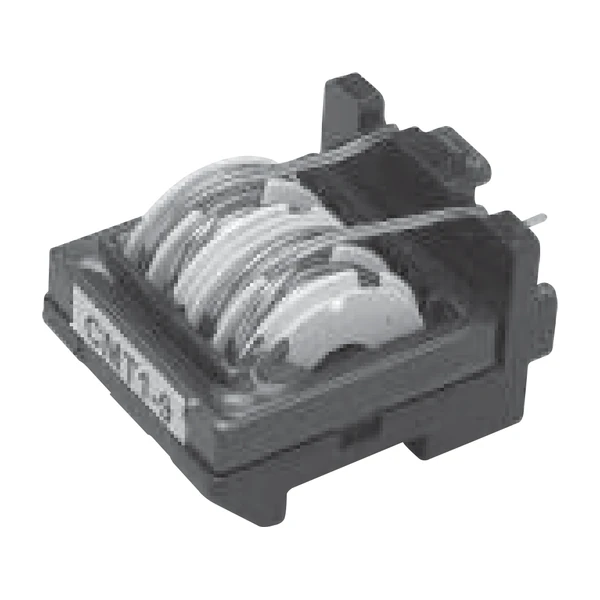
CTX01-19603 is a dual-conductor inductor: two conductors on one core, 375 nH open circuit and 349 nH at full load, for high-current multiphase rails where a single winding would not fit.
- Typical applications: High-current multiphase VRMs, point-of-load converters, server power.
- Pins 2 and 4 are connected through the PCB trace - the layout is part of the circuit on this part, not just a connection.
- Data sheet 4423.
Design Notes
375 nH is at the design point the controller expects of what this series covers. Moving up in inductance costs DCR and saturation current; moving down buys both, at the price of ripple.
The loss budget is the whole story with a power inductor: core loss grows with frequency and flux swing, copper loss grows with current, and the two meet at a different point for every inductance in the series.
Frequently Asked Questions
Should I use OCL or FLL for the ripple calculation?
FLL. OCL is measured at zero bias; under load the core is biased and the inductance drops to the full-load value.
Is this a transformer or an inductor?
Both, depending on how the windings are used. In the intended controller it is a coupled inductor; the coupling is what cancels ripple.
Why is there a tolerance on the DCR?
Winding and termination tolerances. Use the maximum for the loss budget.
Design note: the loop compensation assumes this coupling. Do not substitute a part with a different ratio without the controller vendor's blessing.
Mechanical Dimensions

Dimensional drawing and recommended PCB pad layout from the Eaton data sheet. Tolerances and pad dimensions are as printed on the drawing; check the outline against your layout before release.
Shenzhen Gaorunxin Technology Co., Ltd
Online message
Shenzhen Gaorunxin Technology Co., Ltd