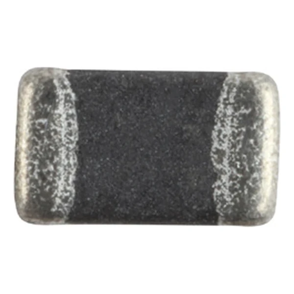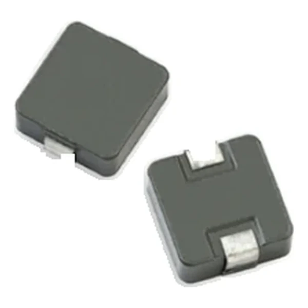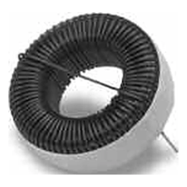
Eaton CTX100-7-52-R 12.0 uH Toroid Inductor, 9.1 A
- Product Details
- Download
Eaton CTX100-7-52-R 12.0 uH Toroid Inductor, 9.1 A
Key Specifications
| Parameter | Value |
|---|---|
| Orderable part number | CTX100-7-52-R |
| Horizontal mount version | CTX100-7-52LP-R |
| Header mount version | 101.40 |
| Inductance | 12.0 uH ±20% |
| Idc | 9.1 A |
| Isat | 54.2 A |
| Volt-time rating | 2960 V-us |
| Energy at Isat | 0.017 uJ |
| Mounting | Through-hole |
| Operating temperature | -40 °C to +105 °C |
| Qualification | Commercial grade |
| RoHS | Compliant, -R suffix |
| Data sheet | Eaton Technical Data 4304 |
Mechanical Drawing

Drawing reproduced from Eaton Technical Data 4304: outline with rated mm dimensions, pad layout and marking. Tolerances are stated on the drawing.
What the Numbers Mean
The winding on a toroid is distributed around the ring, which keeps the leakage field low and makes the part mechanically stable. The trade is assembly cost: the coil has to be wound through the hole, so toroids are hand- or machine-wound rather than printed.
Saturation is reached at 54.2 A. Beyond that point the inductance falls on the soft part of the curve, and the converter’s ripple grows faster than the load current does.
The core stores about 0.017 µJ at saturation, which is the energy available to bridge a load step before the control loop reacts.
The volt-time rating is 2960 V-us: the applied volt-second product that produces a defined core loss. Exceed it and the core heats faster than the copper loss alone would suggest.
Within the CTX100 family this is value 1 of 5, in a range that runs from 12 to 102 uH.
Series Positioning
The toroid family covers microhenry to tens of microhenry at currents up to a few amps, in vertical, horizontal and header-mounted versions of the same core.
- The winding is exposed; check the insulation against the working voltage before mounting the part against a chassis.
- Typical applications: filters; buck and boost switches; chokes.
- Design note: the three mounting variants share one electrical row, so a mechanical change does not require requalifying the magnetics.
Frequently Asked Questions
Why are there three part numbers per row?
Vertical, horizontal and header-mounted versions of the same core and winding. The electrical values are identical; only the mounting differs.
What does the energy column mean?
The energy stored at saturation current, in microjoules. It is the figure that connects inductance and current into a single transient capability.
Why are there three part numbers per row?
Vertical, horizontal and header-mounted versions of the same core and winding. The electrical values are identical; only the mounting differs.
Shenzhen Gaorunxin Technology Co., Ltd
Online message
Shenzhen Gaorunxin Technology Co., Ltd