Eaton DR1050-6R8-R 6.8 uH Shielded Drum Core Inductor
- Product Details
- Download
Eaton DR1050-6R8-R 6.8 uH Shielded Drum Core Inductor
Electrical Specifications
| Parameter | Value |
|---|---|
| Orderable part number | DR1050-6R8-R |
| Rated inductance | 6.8 uH ±20% |
| Open circuit inductance (OCL) | 6.3 uH |
| Irms (40 °C rise) | 5.45 A |
| Isat | 5.8 A |
| DCR typical @ 20 °C | 13 mOhm |
| DCR maximum @ 20 °C | 17 mOhm |
| K-factor (Bp-p = K x L x dI) | 6.82 |
| Package | 10.5 x 10.3 mm footprint, 5.0 mm height |
| Mounting | Surface mount |
| Operating temperature | -40 °C to +125 °C |
| Qualification | Commercial grade |
| RoHS | Compliant (-R suffix) |
How to Read These Ratings
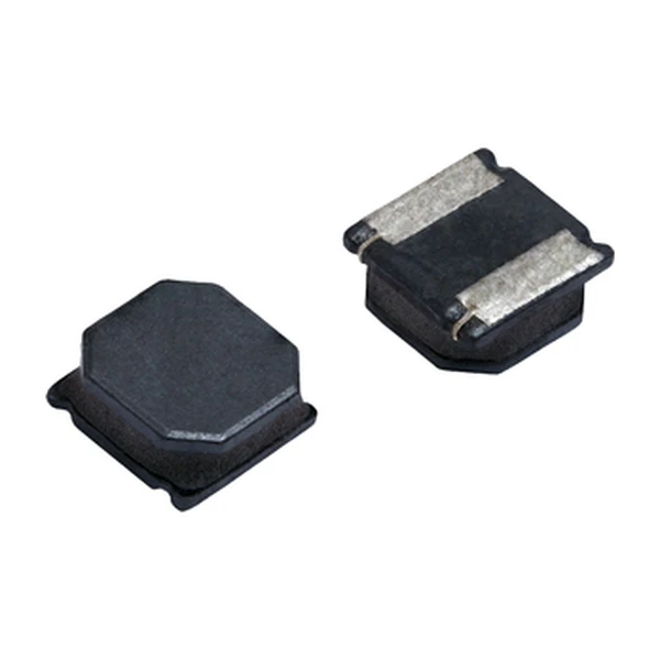
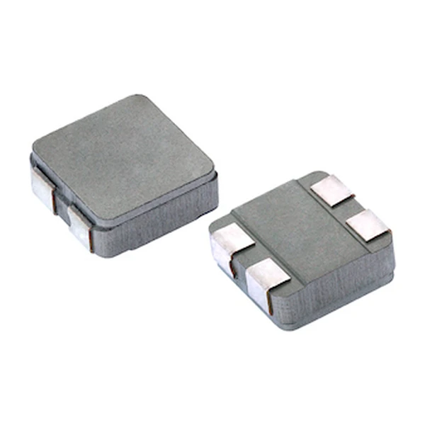
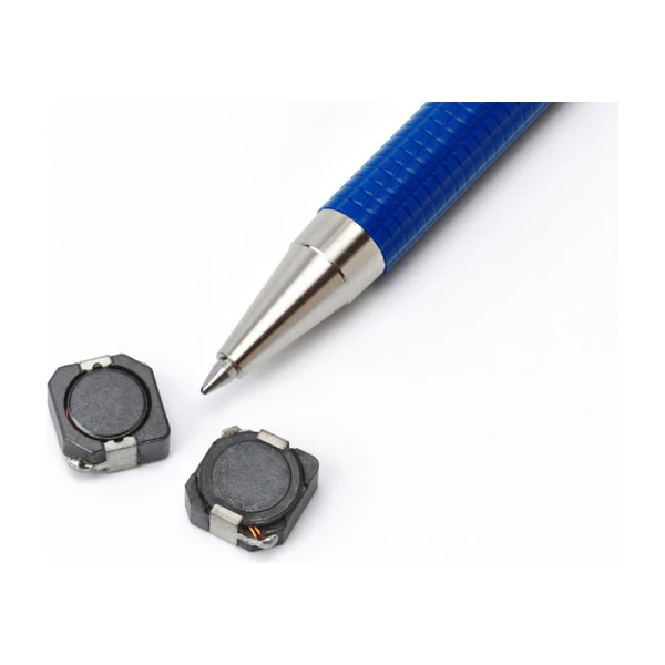
This is a surface-mount drum core with a ferrite shield. The winding sits in a pot core so the flux path closes through ferrite rather than through air, which raises the inductance for a given winding and keeps the radiated field small enough to sit next to a sensitive node.
DCR 13 mOhm is the conduction loss: at the rated current it dissipates about 0.39 W, and that heat has to leave through the terminals and the board.
Isat is the peak current for approximately 35% rolloff at +25 °C. In a buck converter the inductor current peaks at the top of the ripple, so the peak - not the average - is the number that has to stay below Isat with margin for the transient.
What This Family Is For
The DR1050 is the tallest of the 10.5 x 10.3 mm family, and the one that reaches 1000 uH. Where the 3.0 mm part runs out of copper, the 5.0 mm body keeps the winding cool enough to hold its rating.
- Typical applications: Server and desktop power supplies, LED/LCD backlighting, graphics cards, point-of-load modules, printers and peripherals.
- The extra height buys current, not saturation - check Isat separately, because a taller core does not automatically mean a higher flux limit.
- Data sheet 4139.
Sizing and Layout Notes
6.8 uH is in the middle of what this series covers. Moving up in inductance costs DCR and saturation current; moving down buys both, at the price of ripple.
The loss budget is the whole story with a power inductor: core loss grows with frequency and flux swing, copper loss grows with current, and the two meet at a different point for every inductance in the series.
Frequently Asked Questions
Can I run it above the rated current?
Briefly, if the peak stays below Isat and the average heating stays within the temperature rise the board can actually remove. There is no built-in protection.
Is the "-R" suffix important?
Yes - it denotes the RoHS-compliant build. The same inductance without it is a different ordering code.
What is the K-factor for?
It converts the peak-to-peak ripple into a flux swing: Bp-p = K x L x dI, with Bp-p in mT and L in uH. That flux swing is what you enter on the core loss graph.
Design note: use the maximum DCR for the loss budget, keep the peak current below Isat with margin for the transient, and remember the 40 °C rise assumes free air on the recommended pad.
Mechanical Dimensions

Dimensional drawing and recommended PCB pad layout from the Eaton data sheet. Tolerances and pad dimensions are as printed on the drawing; check the outline against your layout before release.
Shenzhen Gaorunxin Technology Co., Ltd
Online message
Shenzhen Gaorunxin Technology Co., Ltd