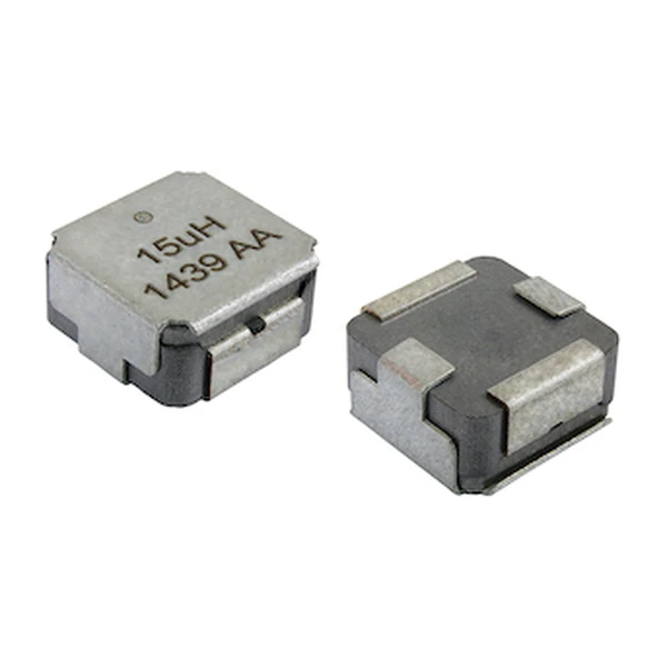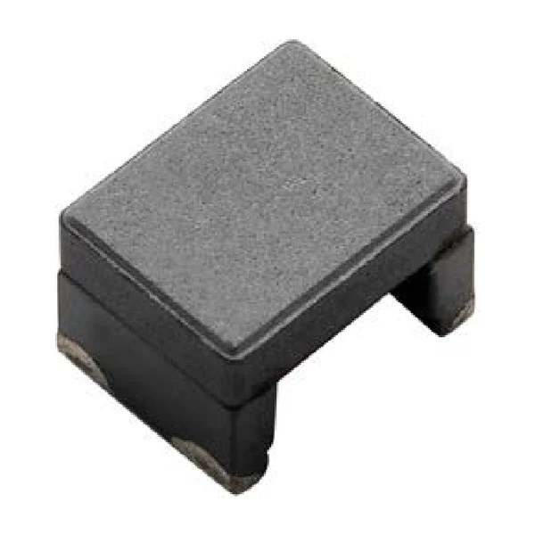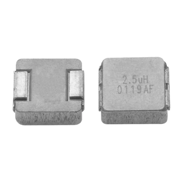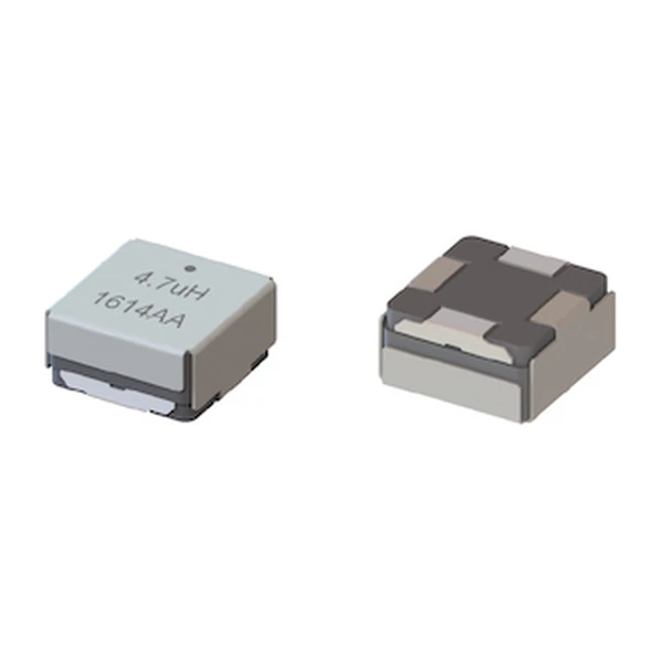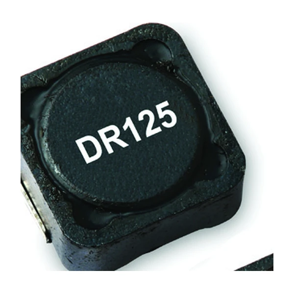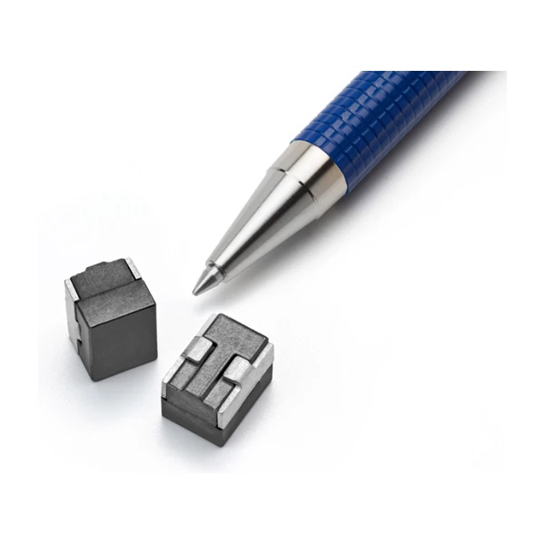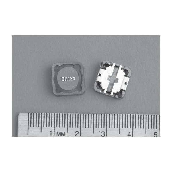
Eaton DR124-R47-R 0.47 uH Shielded Drum Core Inductor
- Product Details
- Download
Eaton DR124-R47-R 0.47 uH Shielded Drum Core Inductor
Key Specifications
| Parameter | Value |
|---|---|
| Orderable part number | DR124-R47-R |
| Rated inductance | 0.47 uH ±20% |
| Open circuit inductance (OCL) | 0.42 uH |
| Irms (40 °C rise) | 16 A |
| Isat | 24.4 A |
| DCR typical @ 20 °C | 2.2 mOhm |
| DCR maximum @ 20 °C | 2.7 mOhm |
| K-factor (Bp-p = K x L x dI) | 17.5 |
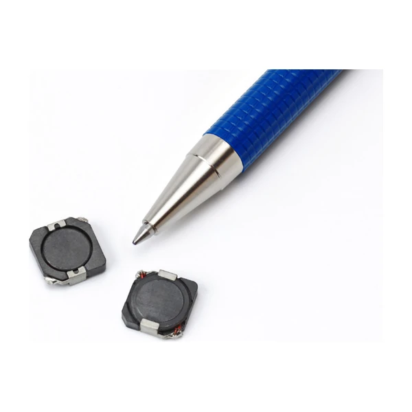
| Package | 12.5 x 12.5 x 4.5 mm |
| Mounting | Surface mount |
| Operating temperature | -40 °C to +125 °C |
| Qualification | Commercial grade |
| RoHS | Compliant (-R suffix) |
How to Read These Ratings
This is a surface-mount drum core with a ferrite shield. The winding sits in a pot core so the flux path closes through ferrite rather than through air, which raises the inductance for a given winding and keeps the radiated field small enough to sit next to a sensitive node.
The DC resistance sets the efficiency floor. 2.2 mOhm at 20 °C rises by roughly a third at 100 °C in copper, so the loss at the hot corner is the number to budget with.
Isat is a magnetic limit, not a thermal one. Isat is the peak current for approximately 25% rolloff at +25 °C. Past it the inductance falls and the ripple climbs, and the current keeps flowing - nothing protects the switch except your own design margin.
What This Family Is For
The DR124 is the 4.5 mm low-profile member of the 12.5 mm DR family: 0.47 uH to 1000 uH in a body that stays under 5 mm, with current up to 24.4 A. It is the part you reach for when the board is thin but the rail is not small.
- Typical applications: Notebook power, LCD panels, desktop and servers, DVD players, DC-DC converters, buck/boost/forward/resonant topologies, noise filtering.
- Frequency range is quoted to 1 MHz - above that the core loss climbs faster than the ripple benefit, and the DCR is no longer the dominant term.
- Data sheet 4141.
Putting It to Work
At 0.47 uH this part is at the low end of the family. The winding that produces that inductance is also what sets the 2.2 mOhm DCR - more turns, thinner wire, more resistance.
Thermal design is not optional here. The rated current assumes a 40 °C rise with the part in free air on a stated pad; inside a closed box, on a thin board, next to a hot IC, that assumption is gone.
Frequently Asked Questions
What is the K-factor for?
It converts the peak-to-peak ripple into a flux swing: Bp-p = K x L x dI, with Bp-p in mT and L in uH. That flux swing is what you enter on the core loss graph.
Why does the DCR have a typical and a maximum?
Winding resistance varies with wire tolerance and termination. The maximum is the guaranteed limit and the one to use for a loss budget that has to hold in production.
Is the "-R" suffix important?
Yes - it denotes the RoHS-compliant build. The same inductance without it is a different ordering code.
Design note: use the maximum DCR for the loss budget, keep the peak current below Isat with margin for the transient, and remember the 40 °C rise assumes free air on the recommended pad.
Mechanical Dimensions

Dimensional drawing and recommended PCB pad layout from the Eaton data sheet. Tolerances and pad dimensions are as printed on the drawing; check the outline against your layout before release.
Shenzhen Gaorunxin Technology Co., Ltd
Online message
Shenzhen Gaorunxin Technology Co., Ltd