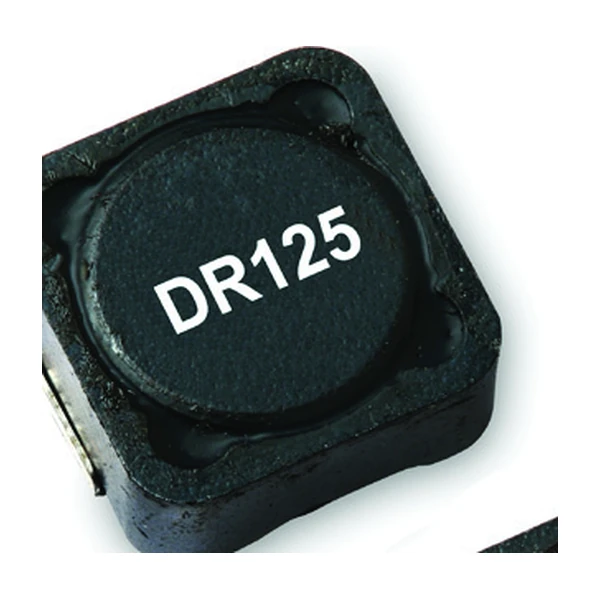
Eaton DR125-471-R 470 uH Shielded Drum Core Inductor
- Product Details
- Download
Eaton DR125-471-R 470 uH Shielded Drum Core Inductor
Ratings at a Glance
| Parameter | Value |
|---|---|
| Orderable part number | DR125-471-R |
| Rated inductance | 470 uH ±20% |
| Open circuit inductance (OCL) | 473 uH |
| Irms (40 °C rise) | 0.87 A |
| Isat | 1.02 A |
| DCR typical @ 20 °C | 718 mOhm |
| Volt-microsecond rating | 102 V-us |
| Package | 12.5 x 12.5 mm footprint, 6.0 mm max height |
| Mounting | Surface mount |
| Operating temperature | -40 °C to +125 °C |
| Qualification | Commercial grade |
| RoHS | Compliant (-R suffix) |
Reading the Data Sheet
The drum core is the workhorse of DC-DC magnetics. It is cheap to build, it saturates in a predictable way, and with a ferrite shield over the winding it can be placed within a few millimetres of an IC without the field coupling into the die.
Copper loss grows with the square of the current, so 718 mOhm matters most at full load. At half the rated current the winding loss drops to a quarter - which is why the part looks oversized for a light-load profile.
Isat is the peak current for approximately 30% rolloff at +20 °C. In a buck converter the inductor current peaks at the top of the ripple, so the peak - not the average - is the number that has to stay below Isat with margin for the transient.
Positioning in the Range
DR125 is the 6.0 mm member of the 12.5 mm family, with current up to 45 A peak. The larger body spreads the winding over more copper, which is where the current headroom comes from.
- Typical applications: Desktop and servers, DC-DC converters, LCD panels, portable and handheld devices, noise filtering and filter chokes.
- Peak current and RMS current are different limits on this series; the ripple current adds heating without adding output, so design to Irms for temperature and Isat for headroom.
- Data sheet 4315.
Design Notes
At 470 uH this part is in the middle of the family. The winding that produces that inductance is also what sets the 718 mOhm DCR - more turns, thinner wire, more resistance.
Efficiency is set by where you sit on the loss curve, and the curve moves with switching frequency. A part that is excellent at 300 kHz can be mediocre at 1 MHz with the same current, because the core loss term takes over.
Frequently Asked Questions
What is the K-factor for?
It converts the peak-to-peak ripple into a flux swing: Bp-p = K x L x dI, with Bp-p in mT and L in uH. That flux swing is what you enter on the core loss graph.
Can I run it above the rated current?
Briefly, if the peak stays below Isat and the average heating stays within the temperature rise the board can actually remove. There is no built-in protection.
What is the K-factor for?
It converts the peak-to-peak ripple into a flux swing: Bp-p = K x L x dI, with Bp-p in mT and L in uH. That flux swing is what you enter on the core loss graph.
Design note: use the maximum DCR for the loss budget, keep the peak current below Isat with margin for the transient, and remember the 40 °C rise assumes free air on the recommended pad.
Mechanical Dimensions

Dimensional drawing and recommended PCB pad layout from the Eaton data sheet. Tolerances and pad dimensions are as printed on the drawing; check the outline against your layout before release.
Shenzhen Gaorunxin Technology Co., Ltd
Online message
Shenzhen Gaorunxin Technology Co., Ltd