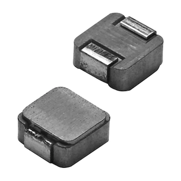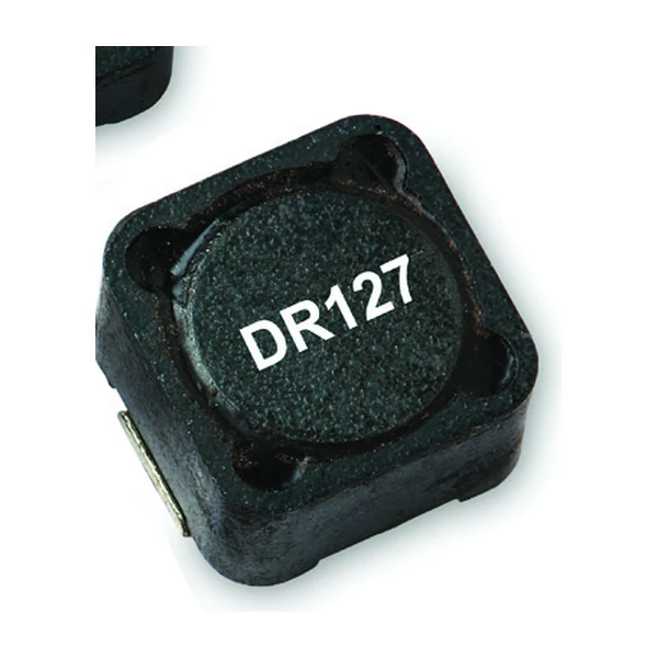
Eaton DR127-1R0-R 1 uH Shielded Power Inductor, 15.5 A
- Product Details
- Download
Eaton DR127-1R0-R 1 uH Shielded Power Inductor, 15.5 A
Electrical Specifications
| Parameter | Value |
|---|---|
| Orderable part number | DR127-1R0-R |
| Rated inductance | 1 uH ±20% |
| Open circuit inductance (OCL) | 0.82 uH |
| Irms (40 °C rise) | 15.5 A |
| Isat | 40 A |
| DCR typical @ 20 °C | 3.13 mOhm |
| Volt-microsecond rating | 4.9 V-us |
| Package | 12.5 x 12.5 mm footprint, 8.0 mm max height |
| Mounting | Surface mount |
| Operating temperature | -40 °C to +125 °C |
| Qualification | Commercial grade |
| RoHS | Compliant (-R suffix) |
How to Read These Ratings
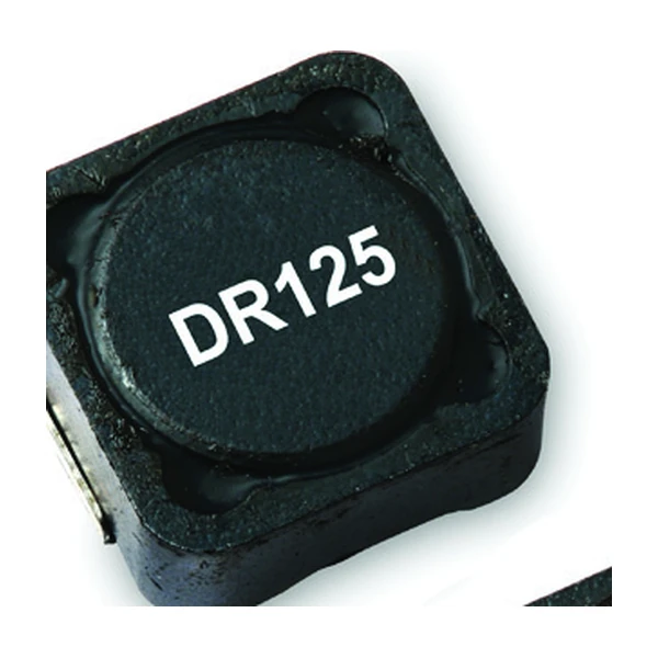
A drum core inductor is a coil wound on a bobbin inside a ferrite pot, and the pot is what makes it usable on a switching board: the field stays inside the core instead of spraying across the PCB. That shielding is the difference between a rail that passes emissions and one that needs another filter stage.
The DC resistance sets the efficiency floor. 3.13 mOhm at 20 °C rises by roughly a third at 100 °C in copper, so the loss at the hot corner is the number to budget with.
The saturation current is measured at a defined roll-off, and Eaton states the percentage on the data sheet: Isat is the peak current for approximately 30% rolloff at +20 °C. Read the number with the percentage in hand, because "saturation" means different things at 25% and at 40%.
Where This Series Fits
DR127 is the 8.0 mm tall version of the 12.5 mm DR family and the one that carries the highest current in the range, up to 56 A peak. Same pad as DR125, more height, more copper, more current.
- Typical applications: High current DC-DC converters, servers and desktop power, graphics cards, battery powered systems, filter chokes.
- At 8 mm the part is tall enough to matter for mechanical clearance and for airflow around neighbouring components - check both before layout.
- Data sheet 4315.
Putting It to Work
1 uH sits in the middle of the range, and the trade at that point is explicit: 3.13 mOhm of DCR against 40 A of saturation headroom.
The loss budget is the whole story with a power inductor: core loss grows with frequency and flux swing, copper loss grows with current, and the two meet at a different point for every inductance in the series.
Frequently Asked Questions
What is the difference between OCL and rated inductance?
OCL is measured at zero DC bias. The rated inductance is the value the part still has at its rated current, and that is what the ripple calculation needs.
How is it mounted?
Surface mount, reflow compatible and J-STD-020 compliant. The pad layout on the data sheet is the one the ratings were measured on.
Why does the DCR have a typical and a maximum?
Winding resistance varies with wire tolerance and termination. The maximum is the guaranteed limit and the one to use for a loss budget that has to hold in production.
Design note: use the maximum DCR for the loss budget, keep the peak current below Isat with margin for the transient, and remember the 40 °C rise assumes free air on the recommended pad.
Mechanical Dimensions

Dimensional drawing and recommended PCB pad layout from the Eaton data sheet. Tolerances and pad dimensions are as printed on the drawing; check the outline against your layout before release.
Shenzhen Gaorunxin Technology Co., Ltd
Online message
Shenzhen Gaorunxin Technology Co., Ltd