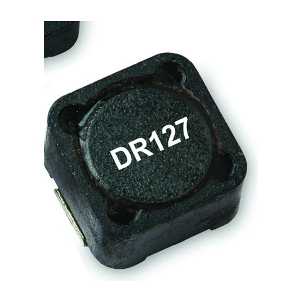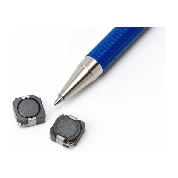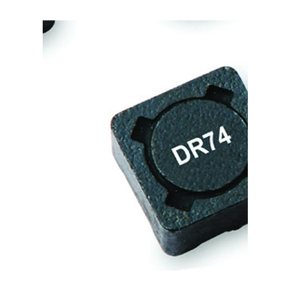
Eaton DR74-470-R - 47 uH 1.15 A Shielded Inductor
- Product Details
- Download
Eaton DR74-470-R - 47 uH 1.15 A Shielded Inductor
Electrical Specifications
| Parameter | Value |
|---|---|
| Orderable part number | DR74-470-R |
| Rated inductance | 47 uH ±20% |
| Open circuit inductance (OCL) | 49.6 uH |
| Irms (40 °C rise) | 1.15 A |
| Isat | 1.41 A |
| DCR typical @ 20 °C | 216 mOhm |
| Volt-microsecond rating | 22.2 V-us |
| Package | 7.6 x 7.6 mm footprint, 4.35 mm max height |
| Mounting | Surface mount |
| Operating temperature | -40 °C to +125 °C |
| Qualification | Commercial grade |
| RoHS | Compliant (-R suffix) |
The Figures Explained
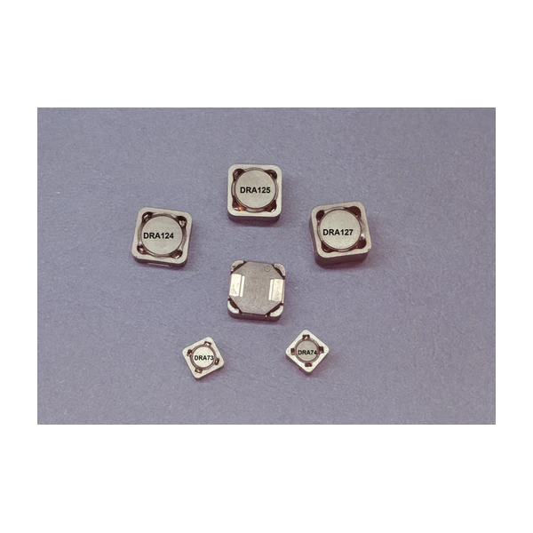
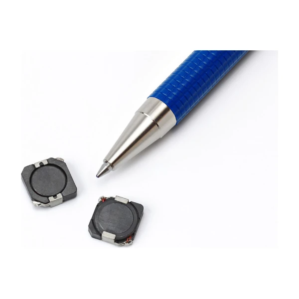
Every part on this page is a shielded drum core: a winding on a ferrite bobbin, capped by a ferrite shield. The construction sets both the inductance and the saturation behaviour, and it is why the same footprint can cover two decades of inductance without changing the land pattern.
The DC resistance sets the efficiency floor. 216 mOhm at 20 °C rises by roughly a third at 100 °C in copper, so the loss at the hot corner is the number to budget with.
Isat is a magnetic limit, not a thermal one. Isat is the peak current for approximately 30% rolloff at +20 °C. Past it the inductance falls and the ripple climbs, and the current keeps flowing - nothing protects the switch except your own design margin.
Where This Series Fits
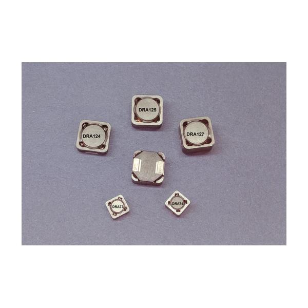
DR74 uses the same 7.6 x 7.6 mm pad as DR73 but stands 4.35 mm tall instead of 3.55 mm. The extra height is what allows the higher current ratings in this size class without changing the land pattern.
- Typical applications: Desktop and servers, DVD and media players, portable devices, LCD panels, DC-DC converters, buck and boost stages.
- Because the footprint matches DR73, a current upgrade can be a straight swap - verify the clearance above the part before you commit to the taller body.
- Data sheet 4315.
Putting It to Work
47 uH is in the middle of what this series covers. Moving up in inductance costs DCR and saturation current; moving down buys both, at the price of ripple.
Efficiency is set by where you sit on the loss curve, and the curve moves with switching frequency. A part that is excellent at 300 kHz can be mediocre at 1 MHz with the same current, because the core loss term takes over.
Frequently Asked Questions
What is the K-factor for?
It converts the peak-to-peak ripple into a flux swing: Bp-p = K x L x dI, with Bp-p in mT and L in uH. That flux swing is what you enter on the core loss graph.
Is Isat a thermal limit?
No. Isat is where the core starts to saturate and the inductance falls by the stated percentage. Temperature is governed by Irms and the board, separately.
How is it mounted?
Surface mount, reflow compatible and J-STD-020 compliant. The pad layout on the data sheet is the one the ratings were measured on.
Design note: use the maximum DCR for the loss budget, keep the peak current below Isat with margin for the transient, and remember the 40 °C rise assumes free air on the recommended pad.
Mechanical Dimensions

Dimensional drawing and recommended PCB pad layout from the Eaton data sheet. Tolerances and pad dimensions are as printed on the drawing; check the outline against your layout before release.
Shenzhen Gaorunxin Technology Co., Ltd
Online message
Shenzhen Gaorunxin Technology Co., Ltd