Eaton DRA125-8R2-R - 8.2 uH AEC-Q200 Power Inductor
- Product Details
- Download
Eaton DRA125-8R2-R - 8.2 uH AEC-Q200 Power Inductor
Specification Table
| Parameter | Value |
|---|---|
| Orderable part number | DRA125-8R2-R |
| Rated inductance | 8.2 uH ±20% |
| Open circuit inductance (OCL) | 7.49 uH |
| Irms (40 °C rise) | 6.41 A |
| Isat1 (30% rolloff @ +25 °C) | 7.9 A |
| Isat2 (40% rolloff @ +125 °C) | 6.32 A |
| DCR typical @ 20 °C | 13 mOhm |
| DCR maximum @ 20 °C | 16 mOhm |
| K-factor (Bp-p = K x L x dI) | 42.1 |
| Package | 12.5 x 12.5 mm footprint |
| Mounting | Surface mount |
| Operating temperature | -40 °C to +165 °C |
| Qualification | AEC-Q200 |
| RoHS | Compliant (-R suffix) |
How to Read These Ratings
AEC-Q200 is the entry ticket, not the destination. This part is qualified to the automotive standard and rated to 165 °C ambient plus self-heating, in a shielded drum core built to survive shock and vibration rather than a laboratory bench.
Automotive thermal cycles are the hard part: the part may be rated to 165 °C, but every power cycle flexes the solder joint. The four-terminal variants exist precisely because two terminals are not always enough.
Isat1 is the 30% rolloff point at +25 °C, Isat2 the 40% rolloff at +125 °C. In a buck converter the inductor current peaks at the top of the ripple, so the peak - not the average - is the number that has to stay below Isat with margin for the transient.
What This Family Is For
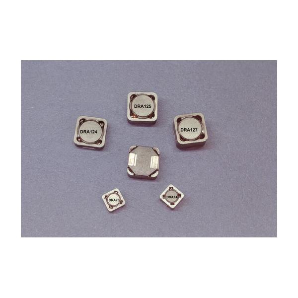
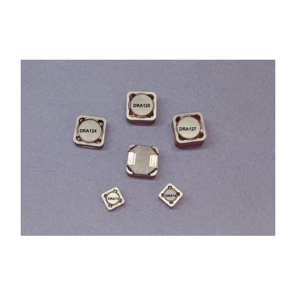
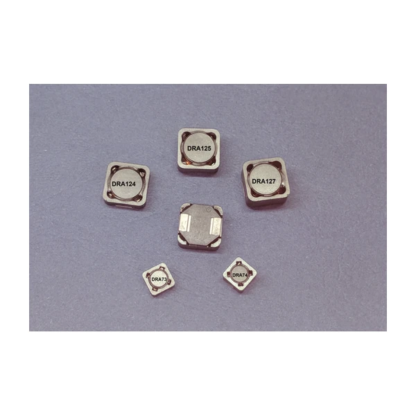
DRA125 is the 12.5 mm AEC-Q200 part at mid height - more current than DRA124, same footprint, so an upgrade does not force a board respin.
- Typical applications: Automotive DC-DC converters, body control modules, LED lighting, ADAS, infotainment supplies.
- Shielding matters in a module full of radios and sensors: the closed drum keeps the field in, but the layout still has to keep the hot loop small.
- Data sheet 4319.
Sizing and Layout Notes
Choose 8.2 uH when the ripple target is in the middle of the design window: the DCR stays at 13 mOhm and the saturation limit at 7.9 A leaves the transient room it needs.
Efficiency is set by where you sit on the loss curve, and the curve moves with switching frequency. A part that is excellent at 300 kHz can be mediocre at 1 MHz with the same current, because the core loss term takes over.
Frequently Asked Questions
Is the part shielded?
Yes, magnetically shielded, which is what keeps the field out of the radios, sensors and ADAS front ends that share the module.
How does it differ from the commercial DR part of the same size?
The electrical shape is similar, the qualification, the temperature range and often the terminal construction are not. Do not assume drop-in equivalence.
Why are there two Isat values?
The first is the 30% roll-off point at +25 °C, the second is the 40% roll-off at +125 °C. Hot ferrite saturates earlier, so the second number is the one to use at temperature.
Design note: the 165 °C rating is ambient plus self-heating. Close the loss budget at the hot corner, with the maximum DCR and the hot Isat figure.
Mechanical Dimensions

Dimensional drawing and recommended PCB pad layout from the Eaton data sheet. Tolerances and pad dimensions are as printed on the drawing; check the outline against your layout before release.
Shenzhen Gaorunxin Technology Co., Ltd
Online message
Shenzhen Gaorunxin Technology Co., Ltd