Eaton ECMS1V0905-701-R - Surface-Mount Common-Mode Choke 700 Ohm
- Product Details
- Download
Eaton ECMS1V0905-701-R - Surface-Mount Common-Mode Choke 700 Ohm
Key Specifications
| Parameter | Value |
|---|---|
| Orderable part number | ECMS1V0905-701-R |
| Impedance minimum @ 100 MHz | 500 Ohm |
| Impedance typical @ 100 MHz | 700 Ohm |
| DCR maximum @ +25 °C | 10 mOhm |
| Rated current maximum | 5 A |
| Rated voltage maximum | 80 Vdc |
| Insulation resistance minimum | 10 MOhm |
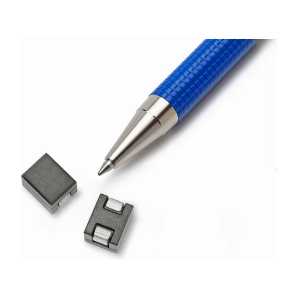
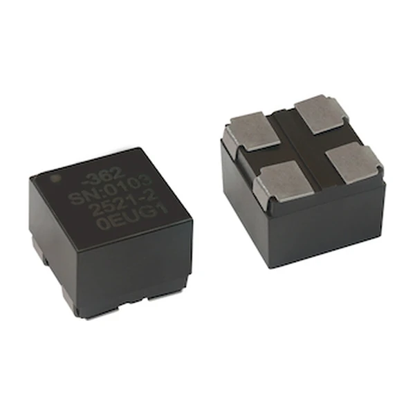
| Package | 10 x 7.5 mm footprint, 4.8 mm height, up to 6 A |
| Mounting | Surface mount |
| Operating temperature | -40 °C to +125 °C |
| Qualification | Commercial grade |
| RoHS | Compliant (-R suffix) |
Outline Drawing

Drawings from the Eaton data sheet: mechanical outline with rated mm dimensions, recommended PCB pad layout, and winding schematic. Tolerances and pad tolerances are stated on the drawing itself.
The Figures Explained
Where a single line needs a differential choke and the board has no room for a filter stage, the common-mode choke is the efficient answer: two windings, one core, and the noise path attenuated in a single component.
Impedance is quoted at 100 MHz with the windings in parallel - the frequency band where switching harmonics actually radiate. The minimum column is the guaranteed production limit; the typical column is what most parts deliver.
The DCR sits in the power path, so every milliohm is loss on the supply lines: 10 mOhm maximum at 5 A is a deliberate trade the family makes against impedance in the same footprint.
The typical and the maximum DCR are both quoted for a reason: production spread. A loss budget that has to hold across a build uses 10 mOhm as the optimistic case and plans against the maximum.
What This Family Is For
ECMS is the surface-mount common-mode family for battery-powered, renewable energy, smart meter and industrial equipment: high-frequency filtering on a closed square core, with current ratings up to 15 A across the three footprints.
- Typical applications: battery backup, renewable energy products, smart meters, LED lighting, industrial IoT, motion controls, power supplies, medical equipment.
- The rated current is a maximum for the winding; at high ambient the thermal budget, not the current column, decides the safe operating point.
- Data sheet ELX1113; footprint 10 x 7.5 mm footprint, 4.8 mm height, up to 6 A.
Putting It to Work
Frequently Asked Questions
Does DC bias affect the impedance?
Modestly. The core is sized so that the rated current does not saturate the path, but large unbalanced DC shifts the operating point - keep the lines balanced.
Why is there a rated voltage for a choke?
The maximum working voltage on the lines the choke sits between. Exceeding it stresses the winding insulation.
What does the impedance number mean?
It is the impedance the choke presents to common-mode noise at 100 MHz, measured with the windings in parallel at +25 °C. The minimum is the guaranteed value; the typical is the centre of the distribution.
Design note: pick the impedance from the noise band you need to attenuate, then verify the rated current covers the DC on both lines combined.
Mechanical Dimensions

Dimensional drawing and recommended PCB pad layout from the Eaton data sheet. Tolerances and pad dimensions are as printed on the drawing; check the outline against your layout before release.
Shenzhen Gaorunxin Technology Co., Ltd
Online message
Shenzhen Gaorunxin Technology Co., Ltd