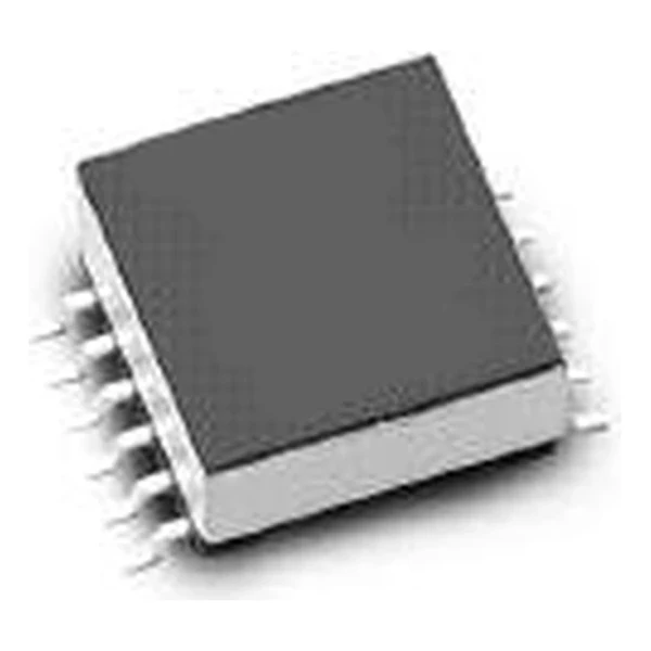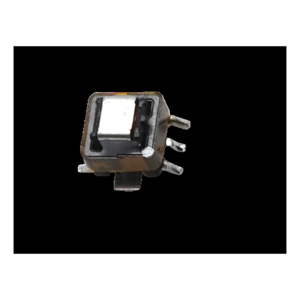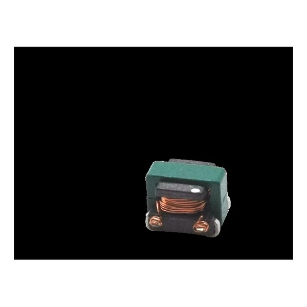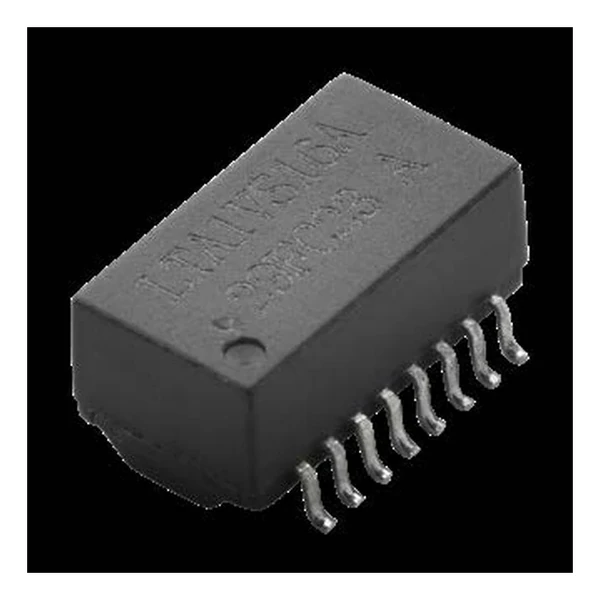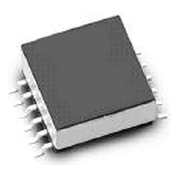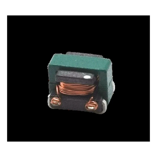
Eaton ECSTA1V0504-1125-R Current Sense Transformer 125:1
- Product Details
- Download
Eaton ECSTA1V0504-1125-R Current Sense Transformer 125:1
Specification Table
| Parameter | Value |
|---|---|
| Orderable part number | ECSTA1V0504-1125-R |
| Turns ratio secondary:primary | 125:1 |
| Secondary inductance minimum | 1280 uH |
| DCR secondary maximum | 13 Ohm |
| DCR primary reference | 3 mOhm |
| Hi-pot primary to secondary | 500 Vac |
| Sensed current maximum | 7 A |
| Package | 4.8 x 3.65 x 3.55 mm |
| Mounting | Surface mount |
| Operating temperature | -40 C to +125 C |
| Qualification | AEC-Q200 |
| RoHS | Compliant, -R suffix |
| Data sheet | Eaton Technical Data ELX1189 |
Outline drawing, winding arrangement and recommended pad layout are on
page 2 of Eaton Technical Data ELX1189; the package line above gives the body size where
the data sheet states it.
How to Read These Ratings
A current sense transformer measures the current in a primary conductor by stepping it down into a burden resistor. The turns ratio sets the scaling, the secondary inductance sets how low in frequency the part still works, and the secondary DCR sets how much of the signal is lost before the resistor sees it.
With a 125:1 ratio, a 10 A primary current becomes 0.08 A in the secondary. Across a 50 ohm burden that is 4 V, which is what the controller actually sees.
The secondary winding of 1280 uH with 13000 mOhm of resistance sets both the low-frequency corner and the signal loss; both move if you change the burden resistor.
Within the ECSTA1V0504 family this is item 8 of 9 in the Eaton catalogue.
Positioning in the Range
The ECST and ECSTA ranges cover 7 A to 15 A of primary current in EE4.4 to EE8.3 packages, with turns ratios from 20:1 to 200:1.
- Never operate with the secondary open. Terminate into the burden resistor before applying primary current.
- Typical applications: motor drive; on-board chargers; dc/dc converters; wireless chargers; battery management systems (bms).
- Design note: the burden resistor and the secondary inductance set the bandwidth. Size the resistor first.
Frequently Asked Questions
Is the part AEC-Q200 qualified?
The ECSTA versions are; the ECST versions are the commercial equivalents with the same electrical ratings.
What turns ratio do I need?
Pick the ratio so the secondary current into the burden resistor gives the voltage the controller expects at the current you want to measure. Higher ratios give more resolution but more secondary inductance and DCR.
What defines the low-frequency limit?
The secondary inductance and the burden resistance form a high-pass corner. Below it the output droops, which is why the inductance is quoted at a stated test frequency.
Shenzhen Gaorunxin Technology Co., Ltd
Online message
Shenzhen Gaorunxin Technology Co., Ltd