Eaton FP0906R1-R15-R 150 nH Power Inductor, 51 A
- Product Details
- Download
FP0906R1-R15-R at a glance: 150 nH high frequency, high current power inductor, 51 A Irms, 65 A Isat, DCR 0.29 mOhm, 9.6 x 6.45 mm body, 8.0 mm tall.
Eaton FP0906R1-R15-R High frequency, high current power inductors
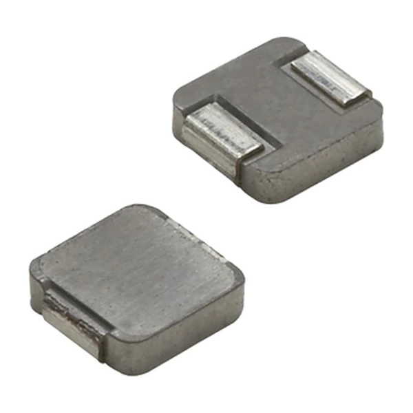
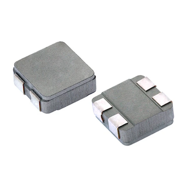
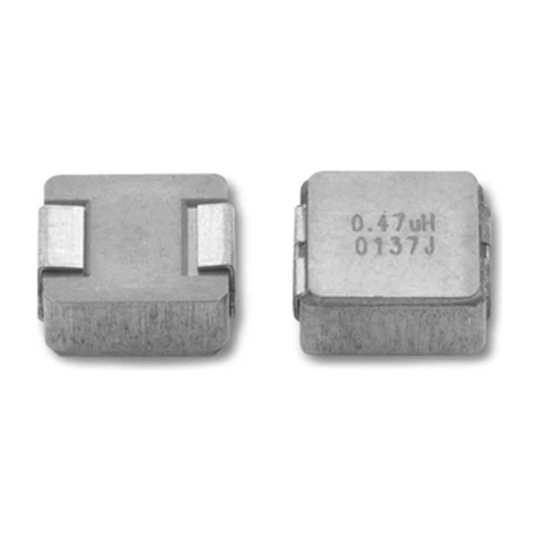
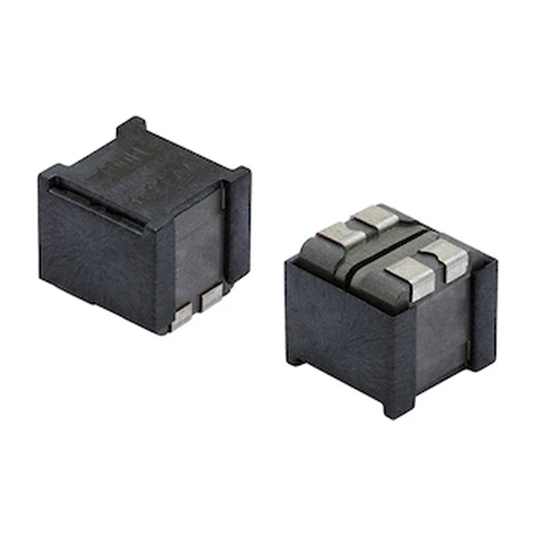
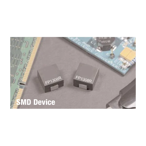
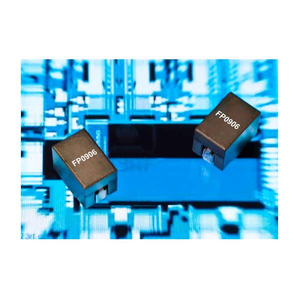
FP0906R1-R15-R is one of Eaton's high frequency, high current power inductor series, 9.6 x 6.45 mm with a 8.0 mm tall profile. Electrically it offers 150 nH at 51 A Irms and 0.29 mOhm typical DCR, which is the combination you want when the rail carries tens of amps and the board has no room for a larger can.
Electrical Specifications
| Orderable part number | FP0906R1-R15-R |
| Inductance, OCL (0 Adc) | 150 nH |
| Inductance, FLL (minimum) | 108 nH |
| Irms (40 °C rise, no core loss) | 51 A |
| Isat (20% roll-off @ +25 °C) | 65 A |
| Isat2 (20% roll-off @ +125 °C) | 55 A |
| DCR typical @ +20 °C | 0.29 mOhm |
| K-factor (Bp-p = K x L x dI) | 451 |
| Package | 9.6 x 6.45 mm, 8.0 mm height |
| Core material | Ferrite, magnetically shielded |
| Operating temperature | -40 °C to +125 °C (ambient plus self-temperature rise) |
| RoHS | Compliant (-R suffix) |
How to Read These Ratings
150 nH open-circuit, 108 nH at full load: that is a 28% roll-off purely from DC bias, before temperature enters the picture. Use the biased figure when you check peak current against saturation, and the unbiased one when you size the ripple.
Saturation is quoted as 20% roll-off at 65 A at +25 °C. That is a convention rather than a cliff: past it the inductance keeps falling, and how quickly depends on how hard the core is driven. Compare your worst-case peak against this number, not the average current.
Copper loss at the rated current works out at about 754 mW (51 A squared times 0.29 mOhm). That is the term the Irms rating measures. The missing term is core loss, and at a few hundred kilohertz it can be the larger of the two.
The K-factor of 451 turns ripple into flux: a peak-to-peak swing of 19.5 A gives about 131.9 mT peak in the core. Read the material loss curve at that flux and your switching frequency to get the loss term Irms leaves out.
Where This Part Sits in the Range
The 9.6 x 6.45 mm body sits in the middle of the FP range: wide enough for a winding with low DCR, compact enough to place next to the switching stage without a long loop back to the input capacitors. At 150 nH this is mid-range for the body: moderate ripple, DCR still low, and comfortable operation across most of the switching-frequency range the data sheet quotes.
That makes it part 3 of 7 when the data sheet is sorted by inductance.
- Application fit: Multi-phase and Vcore regulators, Voltage Regulator Modules (VRMs), Desktop and server VRMs and EVRDs.
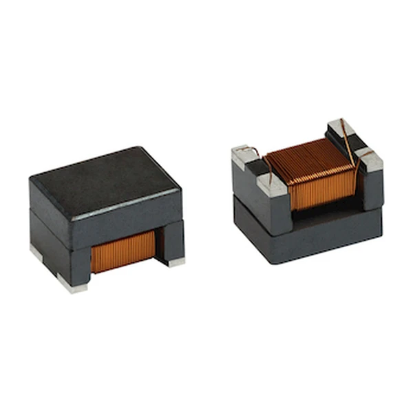
- Construction: ferrite core, magnetically shielded, surface mount, supplied on tape and reel.
- Temperature: -40 °C to +125 °C, ambient plus self-temperature rise.
Sizing It Into a Design
Start from ripple: dI = (Vin - Vout) x D / (L x fsw). With 150 nH and your switching frequency that gives peak current, and the peak is what has to stay under the Isat column for the temperature inside the enclosure. Then check the DC term against Irms.
Two layout points matter with a part this size. Keep the input capacitor loop short, because the switch node is the main source of radiated noise and the inductor will not fix it. And give the pads enough copper: at 0.29 mOhm the winding is not the loss, the trace can be.
Dimensions and Pad Layout
The drawing below is taken from the Eaton data sheet for this series: body outline, recommended pad layout and winding schematic. Pad geometry matters more than usual here, because the terminals are large and the body sits low, so an undersized pad wicks solder and lifts the part off the plane.

Frequently Asked Questions
Can I substitute a lower inductance in the same body?
Only after checking saturation. Lower inductance means higher ripple and a higher peak current for the same DC load. The part with less inductance usually has more saturation headroom, but the ripple penalty is real, so recalculate peak current before substituting.
How is the part packed?
Tape and reel, with the reel quantity stated in the packaging section of the data sheet. The parts are polarised by the terminal marking, so check orientation in the reel before setting up the feeder.
Shenzhen Gaorunxin Technology Co., Ltd
Online message
Shenzhen Gaorunxin Technology Co., Ltd