Eaton FP1308R2-R32-R - 320 nH Shielded Power Inductor 13.4 x 12.7 mm
- Product Details
- Download
FP1308R2-R32-R at a glance: 320 nH high frequency, high current power inductor, 45 A Irms, 52 A Isat, DCR 0.53 mOhm, 13.4 x 12.7 mm body, 8.0 mm tall.
Eaton FP1308R2-R32-R High frequency, high current power inductors
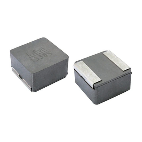
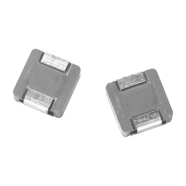
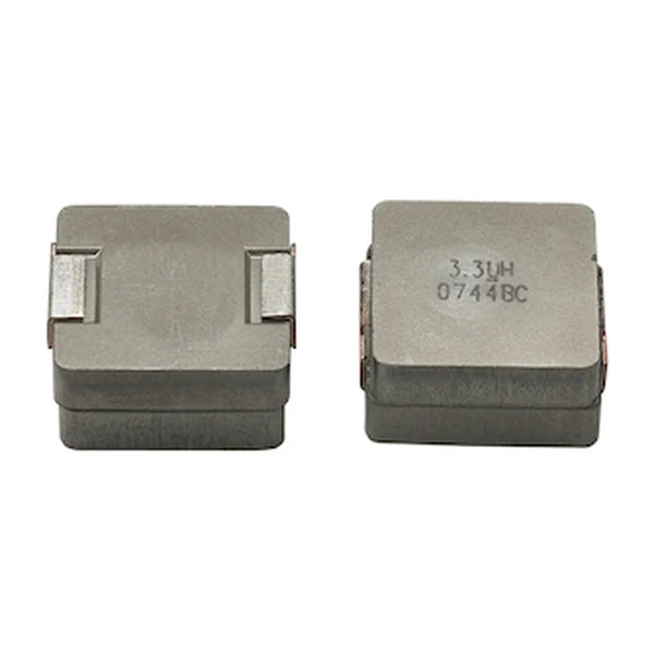
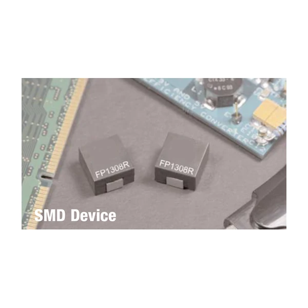
Eaton FP1308R2-R32-R is a high frequency, high current power inductor in a 13.4 x 12.7 mm surface-mount package. It carries 320 nH of open-circuit inductance with 45 A Irms and a typical DCR of 0.53 mOhm, which places it in the switching stage of a multi-phase regulator rather than in bulk energy storage. The body is 8.0 mm tall and rated from -40 °C to +125 °C.
Ratings at a Glance
| Orderable part number | FP1308R2-R32-R |
| Inductance, OCL (0 Adc) | 320 nH |
| Inductance, FLL (minimum) | 230 nH |
| Irms (40 °C rise, no core loss) | 45 A |
| Isat (20% roll-off @ +25 °C) | 52 A |
| Isat2 (20% roll-off @ +125 °C) | 40 A |
| DCR typical @ +20 °C | 0.53 mOhm |
| K-factor (Bp-p = K x L x dI) | 233 |
| Package | 13.4 x 12.7 mm, 8.0 mm height |
| Core material | Ferrite, magnetically shielded |
| Operating temperature | -40 °C to +125 °C (ambient plus self-temperature rise) |
| RoHS | Compliant (-R suffix) |
The Figures Explained
At zero bias the winding measures 320 nH. Put Isat1 through it and the figure falls to 230 nH, about 28% lower, because the ferrite is partly saturated. Ripple calculations belong on the 320 nH number; loop stability and worst-case current belong on the lower one.
The first Isat column, 52 A at +25 °C, is the peak the part takes at 20% roll-off. Note the temperature: run the same part in a hot enclosure and the usable peak drops, which is why the data sheet prints more than one column.
The 1073 mW dissipated at 45 A through 0.53 mOhm is what sets the 40 °C rise behind the Irms column. Because that figure excludes core loss, a converter running at high frequency with large ripple will heat the part more than the table suggests.
Core loss needs flux, and flux here is about 116.3 mT for a 15.6 A ripple (K = 233). Double the ripple and the flux roughly doubles, but the loss does not - it climbs faster than linearly, which is why pushing ripple up to save inductance is not free.
Series Positioning
At 13.4 x 12.7 mm this is one of the larger FP bodies, aimed at high-current rails where a single phase carries enough current that paralleling smaller parts would cost more board area than it saves. At 320 nH this sits at the high-inductance end of the family. Ripple is small and core loss with it, but there is less headroom before saturation, because saturation current falls as inductance rises in the same can.
That makes it part 10 of 15 when the data sheet is sorted by inductance, with the highest DCR in the series at 0.53 mOhm, which is what the extra turns cost, Irms of 45 A is the bottom of the family.
- Application fit: Multi-phase and Vcore regulators.
- Construction: ferrite core, magnetically shielded, surface mount, supplied on tape and reel.
- Temperature: -40 °C to +125 °C, ambient plus self-temperature rise.
Sizing It Into a Design
Start from ripple: dI = (Vin - Vout) x D / (L x fsw). With 320 nH and your switching frequency that gives peak current, and the peak is what has to stay under the Isat column for the temperature inside the enclosure. Then check the DC term against Irms.
On the board, place the part so the switch-node copper is short and wide. At 0.53 of DCR the component is not the resistive bottleneck; the trace and the vias usually are. Thermal vias under the body help more than a bigger copper pour further away.
Dimensions and Pad Layout
The drawing below is taken from the Eaton data sheet for this series: body outline, recommended pad layout and winding schematic. Pad geometry matters more than usual here, because the terminals are large and the body sits low, so an undersized pad wicks solder and lifts the part off the plane.

Frequently Asked Questions
Why does DCR have both a typical and a maximum figure?
The typical value is what the winding measures in production, the maximum is the limit the part is guaranteed to stay under. Size conduction loss on the maximum, because that is the worst case across a production run and over temperature.
Can I substitute a lower inductance in the same body?
Only after checking saturation. Lower inductance means higher ripple and a higher peak current for the same DC load. The part with less inductance usually has more saturation headroom, but the ripple penalty is real, so recalculate peak current before substituting.
Shenzhen Gaorunxin Technology Co., Ltd
Online message
Shenzhen Gaorunxin Technology Co., Ltd