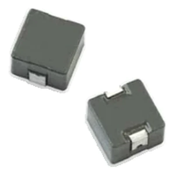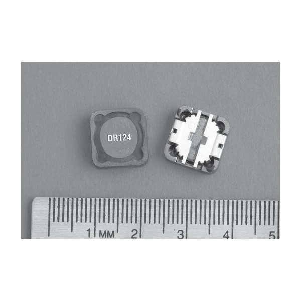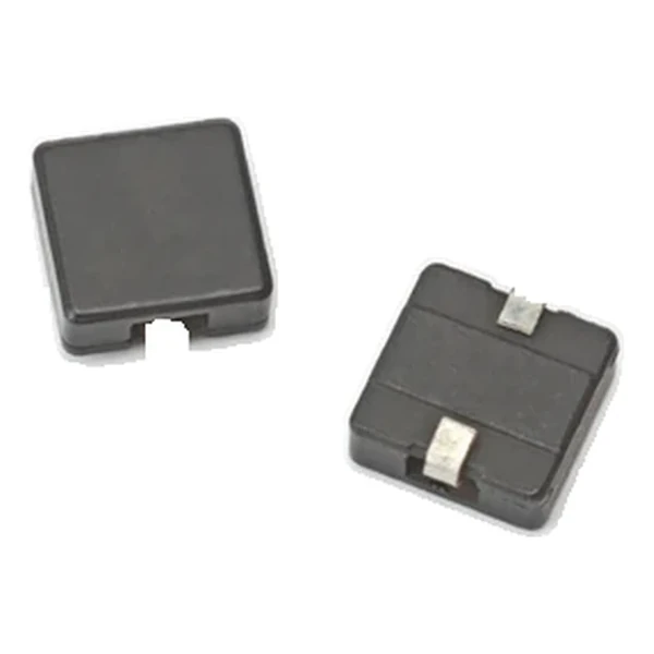
Eaton HC8-5R6-R 5.65 uH SMD Power Inductor, 9.5 V-us
- Product Details
- Download
Eaton HC8-5R6-R 5.65 uH SMD Power Inductor, 9.5 V-us
Specification Table
| Parameter | Value |
|---|---|
| Orderable part number | HC8-5R6-R |
| OCL (open circuit inductance) | 5.65 uH ±20% |
| Irms (DC, 40 °C rise) | 6.7 A |
| Isat (15% rolloff) | 6.9 A |
| Isat2 (30% rolloff) | 12.1 A |
| DCR typical @ +20 °C | 26.3 mOhm |
| Volt-time rating (V-us) | 9.5 |
| Package | 10.9 x 10.4 mm |
| Height | 4.0 mm |
| Mounting | Surface mount |
| Operating temperature | -40 °C to +155 °C (ambient plus self-heating) |
| Qualification | Commercial grade |
| RoHS | Compliant, -R suffix |
| Data sheet | Eaton Technical Data 4120 |
Mechanical Drawing

Drawing reproduced from Eaton Technical Data 4120: outline with
rated mm dimensions, recommended pad layout and winding schematic. Tolerances are stated on
the drawing itself.
How to Read These Ratings
Powder iron is the material choice that gives this family its soft saturation curve and its stable inductance over temperature. There is no thermal aging of the binder, so the inductance you measure on day one is the inductance you have after a thousand thermal cycles.
With 26.3 mOhm typical, the I-squared-R loss at the full 6.7 A rating is about 1.18 W. Compare that against the converter output power before deciding whether the part needs airflow or a copper pour under it.
Saturation is quoted as 15% rolloff. At that point the inductance has fallen to the stated fraction of its nominal value – the part is not damaged there, it simply stops behaving like the inductance on the label. Design the peak current to stay inside that boundary with margin for tolerance.
The core stores roughly 134 uJ at the saturation point – a useful figure when sizing the output capacitance that has to absorb the same transient.
The second saturation column, 12.1 A at 30% rolloff, is the same core taken further into rolloff. The ratio between the two columns is a direct measure of how soft the curve is: a part with a wide gap between them loses inductance slowly and tolerates a larger transient peak.
Series Positioning
The HC powder family sits at the higher-inductance end of the high-current range: from a fraction of a microhenry up to tens of microhenry, on surface-mount bodies with powder iron cores. Every row carries two saturation columns so the rolloff criterion can be chosen explicitly.
Of the 16 values listed for HC8, this is the 9th, in a family covering 0.175 uH to 47.3 uH.
One step down the table, HC8-4R5-R, sits at 4.52 uH with 8 A and 18.6 mOhm – the lower inductance buys about 1.6 A of extra current in the same body.
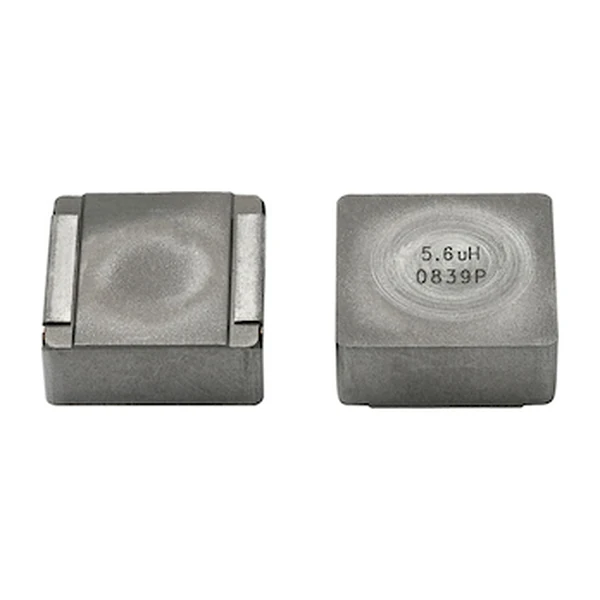
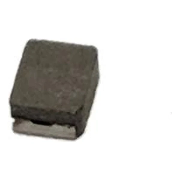
- Core material: powder iron core, 10.9 x 10.4 mm body at 4.0 mm.
- Typical applications: multi-phase regulators; voltage regulator modules (vrms); distributed power systems dc-dc converters; desktop and server vrms and evrds; point-of-load (pol) modules; field programmable gate array (fpga) dc-dc converters.
- The two saturation columns are different criteria, not two measurements of the same thing. Pick the rolloff you can tolerate in the application and stay with that column.
Putting It to Work
Copper resistance rises with temperature, so at the +155 °C limit the maximum DCR of 26.3 mOhm becomes roughly 40.3 mOhm. That is the figure to put into a hot-enclosure loss calculation; the +20 °C column is a bench number.
Design note: use the 30% rolloff column only if the loop can tolerate the inductance droop; the tighter column keeps more inductance at the cost of a lower usable peak current.
- Check that the inductance at the working DC bias still meets the ripple target.
- Check that the inductance at the working DC bias still meets the ripple target.
- Confirm the part marking is visible after placement for traceability.
Frequently Asked Questions
Which saturation column should I design to?
The one that matches the inductance droop your loop can tolerate. The 30 % column gives a higher usable peak current; the tighter column keeps more inductance at the cost of headroom.
Why is the DCR higher than a ferrite part of the same size?
Iron powder has lower permeability, so more turns are needed for the same inductance, and more turns mean more copper. The compensation is the much higher saturation flux density.
Does the inductance drift with age?
The binder is non-organic and the core is not gapped with adhesive, so thermal aging of the magnetic path is not a mechanism here. The value is stable across thermal cycles.
Shenzhen Gaorunxin Technology Co., Ltd
Online message
Shenzhen Gaorunxin Technology Co., Ltd