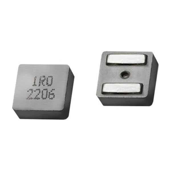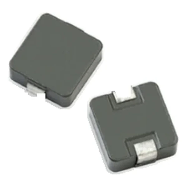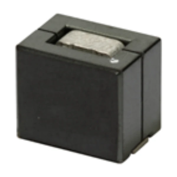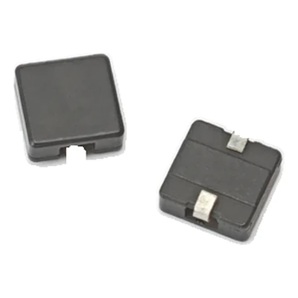
Eaton HC9-4R3-R 4.67 uH High-Current Inductor 5.9 mOhm
- Product Details
- Download
Eaton HC9-4R3-R 4.67 uH High-Current Inductor 5.9 mOhm
Electrical Specifications
| Parameter | Value |
|---|---|
| Orderable part number | HC9-4R3-R |
| OCL (open circuit inductance) | 4.67 uH ±15% |
| Irms (DC, 40 °C rise) | 13 A |
| Isat (20% rolloff) | 13.2 A |
| Isat2 (30% rolloff) | 19.1 A |
| DCR typical @ +20 °C | 5.9 mOhm |
| Volt-time rating (V-us) | 14.4 |
| Package | 13.1 x 14.1 mm |
| Height | 7.5 mm |
| Mounting | Surface mount |
| Operating temperature | -40 °C to +155 °C (ambient plus self-heating) |
| Qualification | Commercial grade |
| RoHS | Compliant, -R suffix |
| Data sheet | Eaton Technical Data DS4312 |
Outline Drawing

Drawing reproduced from Eaton Technical Data DS4312: outline with
rated mm dimensions, recommended pad layout and winding schematic. Tolerances are stated on
the drawing itself.
What the Numbers Mean
The core is iron powder held in a high-temperature non-organic binder. That construction does not saturate abruptly: as current rises the permeability falls progressively, so the inductance droops instead of collapsing. For a switching regulator working near its current limit during a transient, that behaviour keeps the control loop in a known place.
At the rated 13 A the winding dissipates about 0.997 W in copper alone, using the typical DCR of 5.9 mOhm. That figure is the floor of the loss budget: it assumes the current is pure DC, and any ripple adds to it.
The saturation rating reads 20% rolloff. Treat it as the edge of the linear region: below it the inductance is within tolerance, above it the value droops. For a current-mode converter that means the peak current at the worst-case load step is what must fit under this number.
Energy storage at the saturation current is around 407 uJ, the number that connects the inductance and the current rating into a single transient figure.
The second saturation column, 19.1 A at 30% rolloff, is the same core taken further into rolloff. The ratio between the two columns is a direct measure of how soft the curve is: a part with a wide gap between them loses inductance slowly and tolerates a larger transient peak.
What This Family Is For
The HC powder family sits at the higher-inductance end of the high-current range: from a fraction of a microhenry up to tens of microhenry, on surface-mount bodies with powder iron cores. Every row carries two saturation columns so the rolloff criterion can be chosen explicitly.
Of the 12 values listed for HC9, this is the 7th, in a family covering 0.218 uH to 49.2 uH.
Compared with its neighbours in the table, HC9-6R8-R trades 4 A of rated current for the next inductance step, which is the usual compromise in this family.
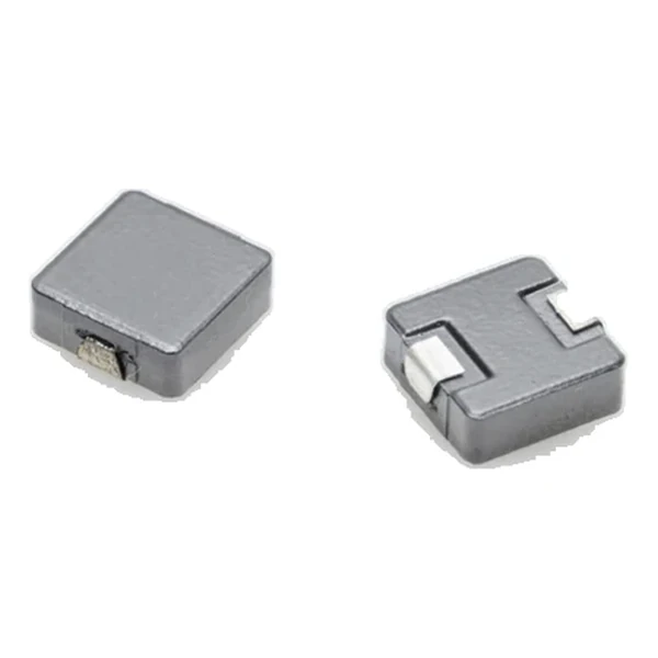
- Core material: powder iron core, 13.1 x 14.1 mm body at 7.5 mm.
- Typical applications: multi-phase regulators; voltage regulator modules (vrms); distributed power systems dc-dc converters; desktop and server vrms and evrds; point-of-load (pol) modules; field programmable gate array (fpga) dc-dc converters.
- The two saturation columns are different criteria, not two measurements of the same thing. Pick the rolloff you can tolerate in the application and stay with that column.
Sizing and Layout Notes
Copper resistance rises with temperature, so at the +155 °C limit the maximum DCR of 5.9 mOhm becomes roughly 9.03 mOhm. That is the figure to put into a hot-enclosure loss calculation; the +20 °C column is a bench number.
Design note: use the 30% rolloff column only if the loop can tolerate the inductance droop; the tighter column keeps more inductance at the cost of a lower usable peak current.
- Check the volt-time rating against the applied V-us at the switching frequency.
- Decide which rolloff column the loop can tolerate, then stay with that column.
- Check the volt-time rating against the applied V-us at the switching frequency.
Frequently Asked Questions
What is soft saturation?
The inductance falls gradually as current rises instead of collapsing at a threshold. A powder core with a distributed gap behaves this way, which keeps the converter stable through a load transient.
What is soft saturation?
The inductance falls gradually as current rises instead of collapsing at a threshold. A powder core with a distributed gap behaves this way, which keeps the converter stable through a load transient.
Which saturation column should I design to?
The one that matches the inductance droop your loop can tolerate. The 30 % column gives a higher usable peak current; the tighter column keeps more inductance at the cost of headroom.
Shenzhen Gaorunxin Technology Co., Ltd
Online message
Shenzhen Gaorunxin Technology Co., Ltd