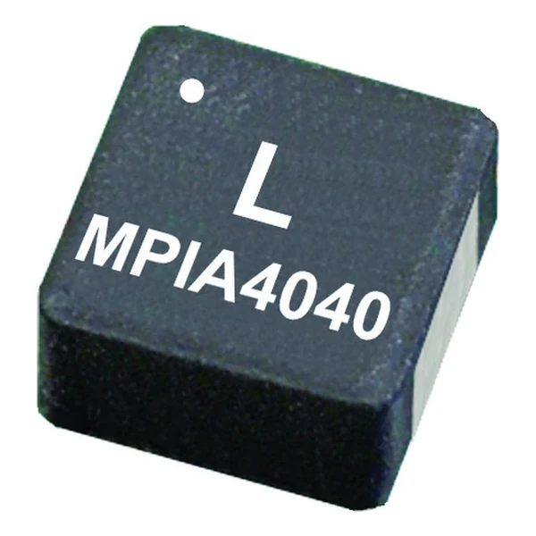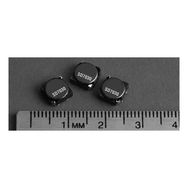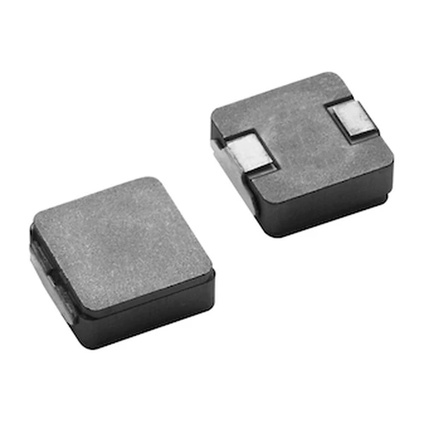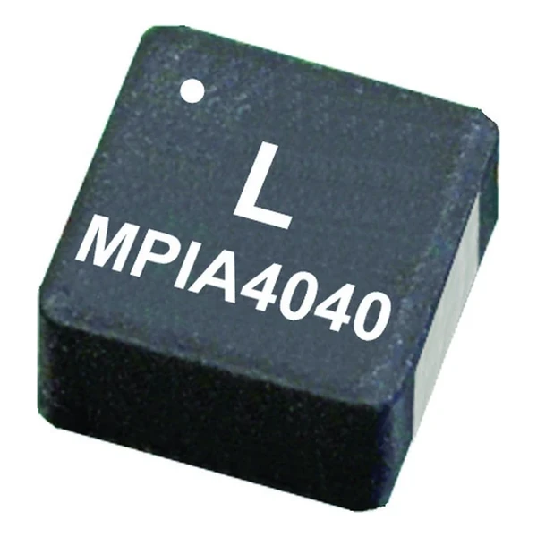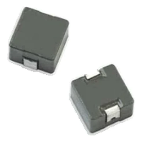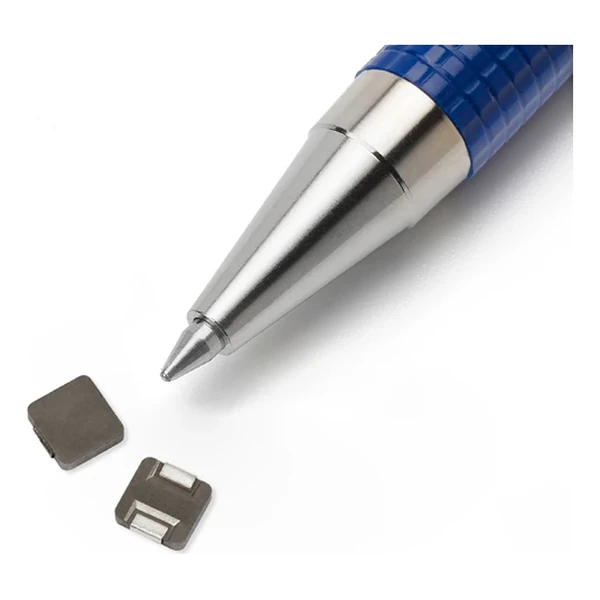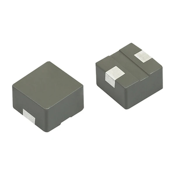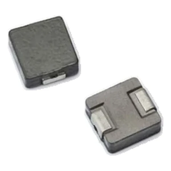
Eaton HCM0703-8R2-R 8.2 uH High-Current Inductor 64 mOhm
- Product Details
- Download
Eaton HCM0703-8R2-R 8.2 uH High-Current Inductor 64 mOhm
Specification Table
| Parameter | Value |
|---|---|
| Orderable part number | HCM0703-8R2-R |
| OCL (open circuit inductance) | 8.2 uH ±20% |
| FLL minimum, at Isat | 4.9 uH |
| Irms (DC, 40 °C rise) | 4 A |
| Isat (20% rolloff @ +25 °C) | 7.5 A |
| DCR typical @ +20 °C | 64 mOhm |
| DCR maximum @ +20 °C | 68 mOhm |
| K-factor (Bp-p = K x L x dI) | 142, Bp-p in Gauss |
| Package | 7.4 x 6.8 mm |
| Height | 3.0 mm |
| Mounting | Surface mount |
| Operating temperature | -55 °C to +125 °C (ambient plus self-heating) |
| Qualification | Commercial grade |
| RoHS | Compliant, -R suffix |
| Data sheet | Eaton Technical Data 4085 |
Mechanical Drawing

Drawing reproduced from Eaton Technical Data 4085: outline with
rated mm dimensions, recommended pad layout and winding schematic. Tolerances are stated on
the drawing itself.
The Figures Explained
This is one of the molded power inductors used across VRM, point-of-load and multiphase regulator designs. The family covers a wide inductance range in standard footprints, and every row is characterised for both typical and maximum DCR so the loss budget can be built either way.
With 64 mOhm typical, the I-squared-R loss at the full 4 A rating is about 1.02 W. Compare that against the converter output power before deciding whether the part needs airflow or a copper pour under it.
Isat is specified as 20% rolloff @ +25 °C, so the number is a rolloff criterion rather than an absolute maximum. The useful working range extends a little beyond it on a soft saturation core, but the loop compensation has to be designed for the inductance that remains.
Stored energy at Isat is about 231 uJ, which is the energy the inductor hands to the load during a transient before the control loop reacts.
The K-factor of 142 converts inductance and ripple into flux swing: each amp of peak-to-peak ripple moves the core through about 1,164 Gauss of Bp-p, the figure the core-loss curve is plotted against.
Series Positioning
The HCM family is the commercial molded range: shielded powder-core parts from a 5.5 mm footprint up to a 17.5 mm body, covering 0.1 uH to tens of microhenry at currents from a few amps to over a hundred.
Within the HCM0703 family this is value 12 of 16, in a range that runs from 0.15 uH to 33 uH.
Compared with its neighbours in the table, HCM0703-100-R trades 1.3 A of rated current for the next inductance step, which is the usual compromise in this family.
- Core material: iron powder core, 7.4 x 6.8 mm body at 3.0 mm.
- Typical applications: voltage regulator module (vrm); multi-phase regulators; point-of-loadmodules; desktop and server vrms and evrds; base station equipment; laptop and notebook regulators.
- The DCR columns are typical and maximum at +20 °C. Copper rises about 0.4 % per °C, so the hot resistance is higher than either column suggests.
Design Notes
Copper resistance rises with temperature, so at the +125 °C limit the maximum DCR of 68 mOhm becomes roughly 96.1 mOhm. That is the figure to put into a hot-enclosure loss calculation; the +20 °C column is a bench number.
Design note: two DCR columns let the loss budget be built either on the typical part or on the worst-case part. Use maximum for a guaranteed thermal design, typical for a nominal one.
- Build the thermal design on the maximum DCR, not the typical one.
- Build the thermal design on the maximum DCR, not the typical one.
- Verify the body height against the enclosure or heat-spreader clearance.
Frequently Asked Questions
Can two parts be stacked for higher current?
Stacking halves the inductance and doubles the current capability in theory, but the two DCRs are not matched and the magnetic coupling is uncontrolled. Use a larger part instead.
Can two parts be stacked for higher current?
Stacking halves the inductance and doubles the current capability in theory, but the two DCRs are not matched and the magnetic coupling is uncontrolled. Use a larger part instead.
What makes a molded inductor different?
The winding is pressed into the magnetic powder with no bobbin or air gap in the path. That is why the body is almost all magnetic material, the DCR is low for the size, and the part is mechanically robust.
Shenzhen Gaorunxin Technology Co., Ltd
Online message
Shenzhen Gaorunxin Technology Co., Ltd