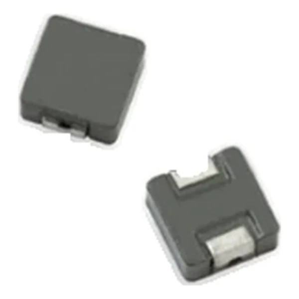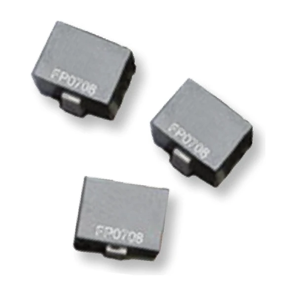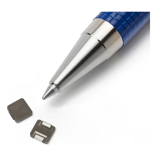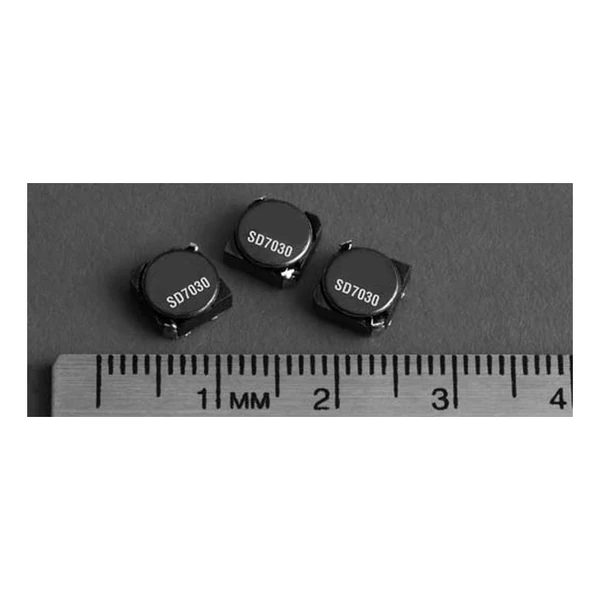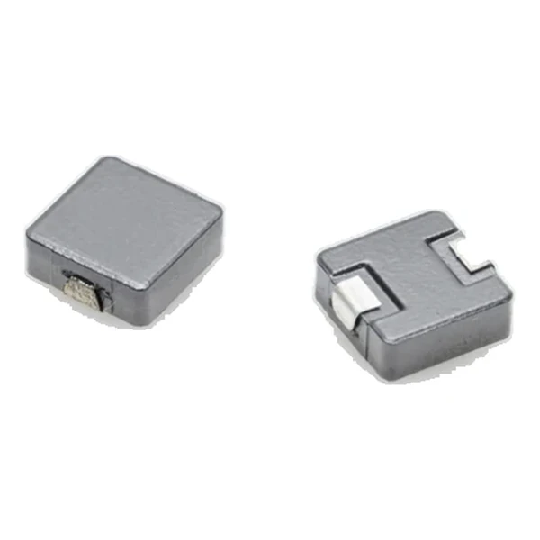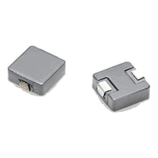
Eaton HCM1305-220-R 22.0 uH Molded Power Inductor, 6.2 A
- Product Details
- Download
Eaton HCM1305-220-R 22.0 uH Molded Power Inductor, 6.2 A
Specification Table
| Parameter | Value |
|---|---|
| Orderable part number | HCM1305-220-R |
| OCL (open circuit inductance) | 22.0 uH ±20% |
| FLL minimum, at Isat | 14.1 uH |
| Irms (DC, 40 °C rise) | 6.2 A |
| Isat (20% rolloff @ +25 °C) | 10 A |
| DCR typical @ +20 °C | 45 mOhm |
| DCR maximum @ +20 °C | 51.8 mOhm |
| K-factor (Bp-p = K x L x dI) | 63, Bp-p in Gauss |
| Package | 13.8 x 12.5 mm |
| Height | 5.0 mm |
| Mounting | Surface mount |
| Operating temperature | -55 °C to +125 °C (ambient plus self-heating) |
| Qualification | Commercial grade |
| RoHS | Compliant, -R suffix |
| Data sheet | Eaton Technical Data 4371 |
Outline Drawing

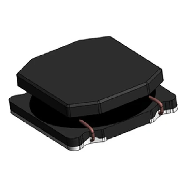
Drawing reproduced from Eaton Technical Data 4371: outline with
rated mm dimensions, recommended pad layout and winding schematic. Tolerances are stated on
the drawing itself.
Reading the Data Sheet
This is one of the molded power inductors used across VRM, point-of-load and multiphase regulator designs. The family covers a wide inductance range in standard footprints, and every row is characterised for both typical and maximum DCR so the loss budget can be built either way.
The DCR figure of 45 mOhm is what sets the efficiency: at 6.2 A the winding drops about 0.279 mV and dissipates 1.73 W. On a low-voltage rail that drop is a measurable fraction of the output, so the DCR column deserves as much attention as the inductance.
Isat is specified as 20% rolloff @ +25 °C, so the number is a rolloff criterion rather than an absolute maximum. The useful working range extends a little beyond it on a soft saturation core, but the loop compensation has to be designed for the inductance that remains.
Energy storage at the saturation current is around 1,100 uJ, the number that connects the inductance and the current rating into a single transient figure.
With K = 63, a peak-to-peak ripple of one amp produces roughly 1,386 Gauss of flux swing. Read the core-loss graph at that amplitude and at the switching frequency to get the core contribution to the total loss.
Series Positioning
The HCM family is the commercial molded range: shielded powder-core parts from a 5.5 mm footprint up to a 17.5 mm body, covering 0.1 uH to tens of microhenry at currents from a few amps to over a hundred.
Within the HCM1305 family this is value 20 of 21, in a range that runs from 0.1 uH to 33 uH.
The next value up in the same family, HCM1305-330-R, gives 33.0 uH at 5.2 A and DCR 74.5 mOhm: the extra inductance costs about 2.5 A of rated current.
- Core material: iron powder core, 13.8 x 12.5 mm body at 5.0 mm.
- Typical applications: voltage regulator module (vrm); multi-phase regulators; point-of-load modules; desktop and server vrms and evrds; base station equipment; notebook and laptop regulators.
- The DCR columns are typical and maximum at +20 °C. Copper rises about 0.4 % per °C, so the hot resistance is higher than either column suggests.
Sizing and Layout Notes
Copper resistance rises with temperature, so at the +125 °C limit the maximum DCR of 51.8 mOhm becomes roughly 73.2 mOhm. That is the figure to put into a hot-enclosure loss calculation; the +20 °C column is a bench number.
Design note: two DCR columns let the loss budget be built either on the typical part or on the worst-case part. Use maximum for a guaranteed thermal design, typical for a nominal one.
- Allow for copper drift: resistance rises with temperature at roughly 0.4 % per °C.
- Allow for copper drift: resistance rises with temperature at roughly 0.4 % per °C.
- Verify the body height against the enclosure or heat-spreader clearance.
Frequently Asked Questions
Can two parts be stacked for higher current?
Stacking halves the inductance and doubles the current capability in theory, but the two DCRs are not matched and the magnetic coupling is uncontrolled. Use a larger part instead.
Is it magnetically shielded?
Yes. The powder core surrounds the winding, so the leakage field is small and the part can sit close to sensitive traces without a shield can.
How much inductance is left at rated current?
That is what the saturation column describes. Isat is the peak current at which inductance has fallen by the stated percentage, so at the rated DC current the part is still inside that boundary.
Shenzhen Gaorunxin Technology Co., Ltd
Online message
Shenzhen Gaorunxin Technology Co., Ltd