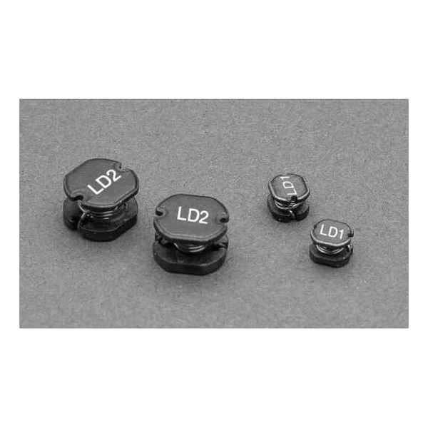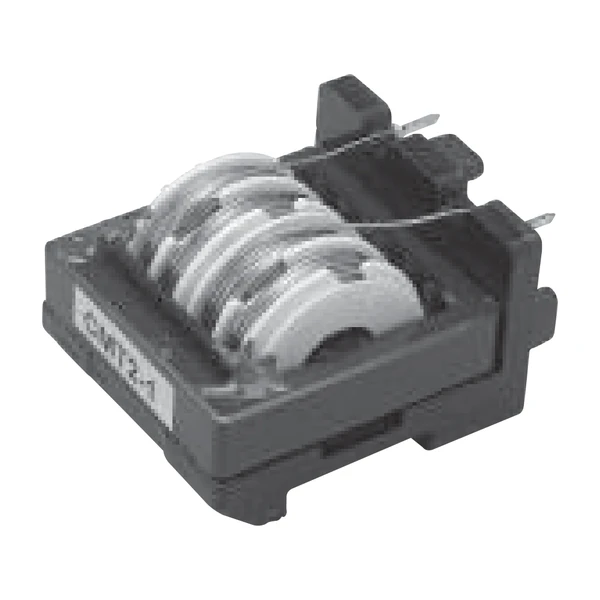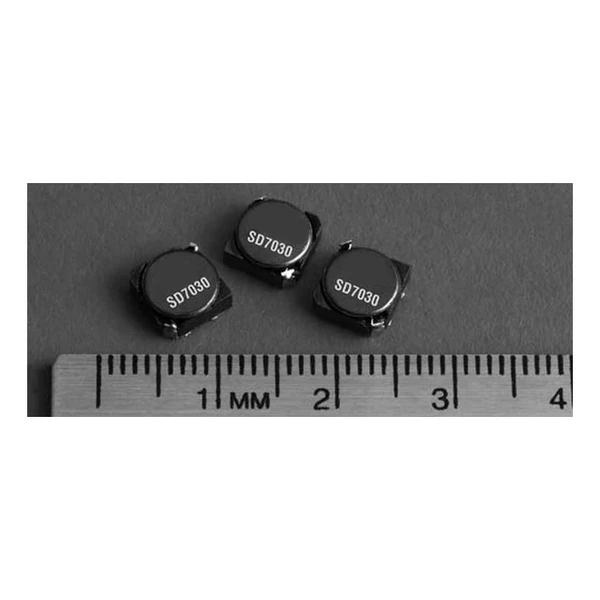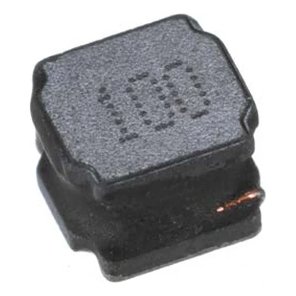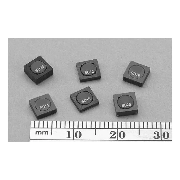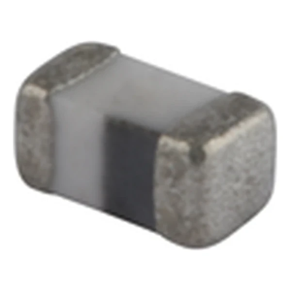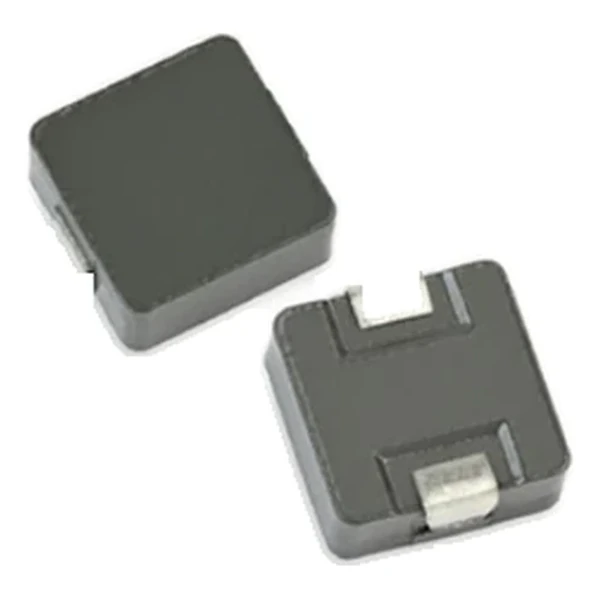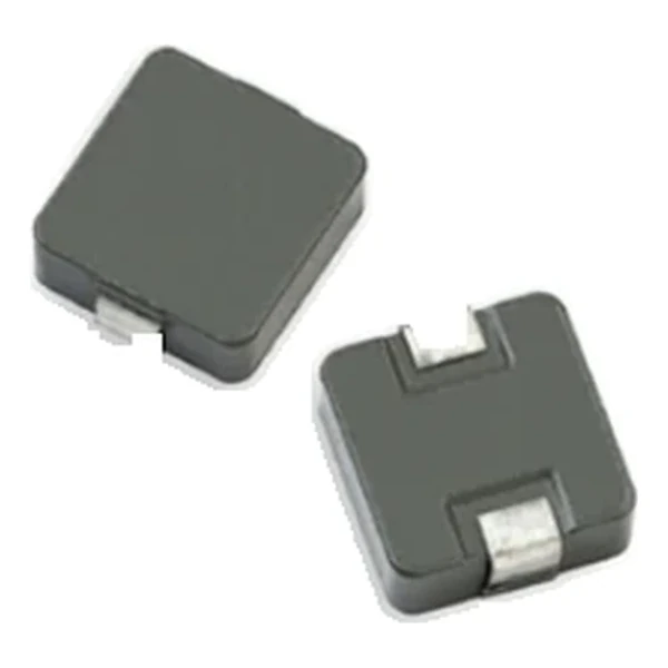
Eaton HCM1A1104V2-150-R 15 uH Automotive Power Inductor
- Product Details
- Download
Eaton HCM1A1104V2-150-R 15 uH Automotive Power Inductor
Key Specifications
| Parameter | Value |
|---|---|
| Orderable part number | HCM1A1104V2-150-R |
| OCL (open circuit inductance) | 15 uH ±20% |
| FLL minimum, at Isat | 9.6 uH |
| Irms (DC, 40 °C rise) | 4.7 A |
| Isat (20% rolloff @ +25 °C) | 4.6 A |
| DCR typical @ +20 °C | 40 mOhm |
| DCR maximum @ +20 °C | 45 mOhm |
| SRF typical | 6.8 MHz |
| K-factor (Bp-p = K x L x dI) | 132, Bp-p in Gauss |
| Package | 11.2 x 10.3 mm |
| Height | 4.0 mm |
| Mounting | Surface mount |
| Operating temperature | -55 °C to +155 °C (ambient plus self-heating) |
| Qualification | AEC-Q200 |
| RoHS | Compliant, -R suffix |
| Data sheet | Eaton Technical Data 10903 |
Mechanical Drawing

Drawing reproduced from Eaton Technical Data 10903: outline with
rated mm dimensions, recommended pad layout and winding schematic. Tolerances are stated on
the drawing itself.
How to Read These Ratings
This is the automotive version of the molded high-current inductor. The body is a molded powder core, the winding is shielded by the magnetic material itself, and the operating range runs to +155 °C. It is the part that goes on the DC-DC stages of body electronics, ADAS modules and infotainment head units.
With 40 mOhm typical, the I-squared-R loss at the full 4.7 A rating is about 0.884 W. Compare that against the converter output power before deciding whether the part needs airflow or a copper pour under it.
Saturation is quoted as 20% rolloff @ +25 °C. At that point the inductance has fallen to the stated fraction of its nominal value – the part is not damaged there, it simply stops behaving like the inductance on the label. Design the peak current to stay inside that boundary with margin for tolerance.
Stored energy at Isat is about 159 uJ, which is the energy the inductor hands to the load during a transient before the control loop reacts.
The K-factor of 132 converts inductance and ripple into flux swing: each amp of peak-to-peak ripple moves the core through about 1,980 Gauss of Bp-p, the figure the core-loss curve is plotted against.
Self-resonant frequency is 6.8 MHz typical. Above that the part becomes capacitive and stops behaving as an inductor, which is why the switching frequency and its first harmonics should stay well below it.
Series Positioning
The HCM1A family is the automotive molded range: AEC-Q200 qualified, rated to +155 °C, from a 5 mm footprint up to a 22 mm body. Several sizes carry a V2 or V3 revision with a higher current rating or an extra saturation column, so the revision letter is part of the specification.
Within the HCM1A1104V2 family this is value 15 of 19, in a range that runs from 0.2 uH to 68 uH.
Compared with its neighbours in the table, HCM1A1104V2-220-R trades 2.2 A of rated current for the next inductance step, which is the usual compromise in this family.
- Core material: alloy powder core, 11.2 x 10.3 mm body at 4.0 mm.
- Typical applications: body electronics; central body control module; vehicle access control system; headlamps, tail lamps and interior lighting and led lighting; heating ventilation and air conditioning controllers (hvac); doors, window lift and seat control.
- The +155 °C rating is ambient plus self-temperature rise. Derate against the hot DCR, not the +20 °C value, when the board sits in a warm enclosure.
Sizing It Into a Design
Copper resistance rises with temperature, so at the +155 °C limit the maximum DCR of 45 mOhm becomes roughly 68.9 mOhm. That is the figure to put into a hot-enclosure loss calculation; the +20 °C column is a bench number.
Design note: the revision letter changes the electrical row. V2 and V3 parts of the same body size are not drop-in substitutes for the base part; compare the tables row by row.
- Verify the qualification and the mounting process match the assembly line.
- Confirm the qualification file covers the module-level test plan.
- Check the hot-corner saturation margin against the worst-case load step.
Frequently Asked Questions
What is the operating temperature range?
The rated range is quoted as ambient plus self-temperature rise, up to the maximum shown in the table. The part is qualified across that span, but the hot corner is where saturation and DCR must be checked.
Why do V2 and V3 parts exist?
They are later revisions of the same body size with a changed electrical row – typically a higher current rating or an extra parameter such as self-resonant frequency. They are separate orderable parts, not substitutes.
What does AEC-Q200 cover?
The qualification regime for passive components in automotive use: thermal shock, temperature cycling, vibration, mechanical shock, moisture resistance and solderability, among others. It qualifies the construction, not the board design.
Shenzhen Gaorunxin Technology Co., Ltd
Online message
Shenzhen Gaorunxin Technology Co., Ltd