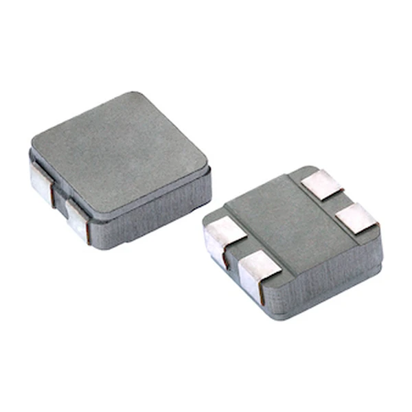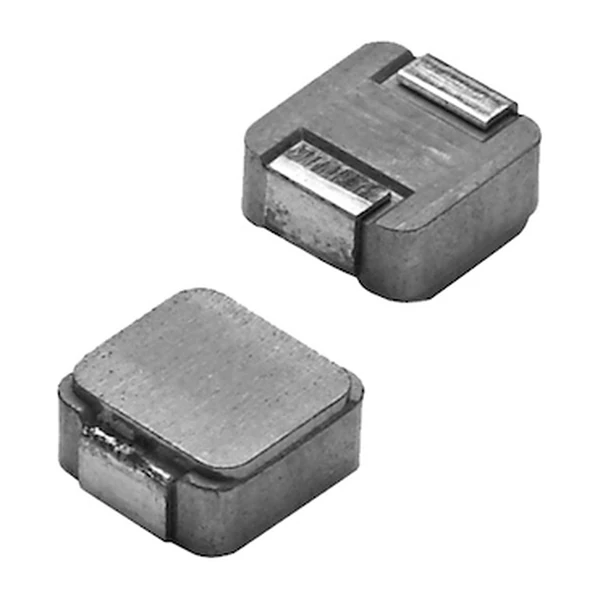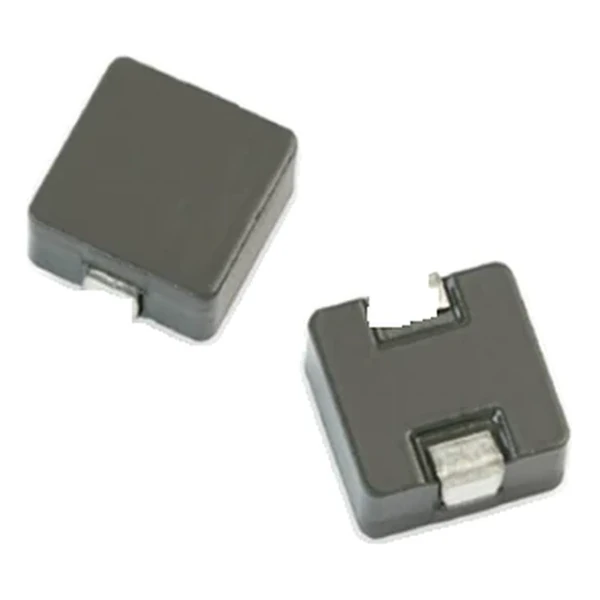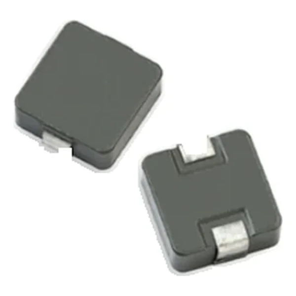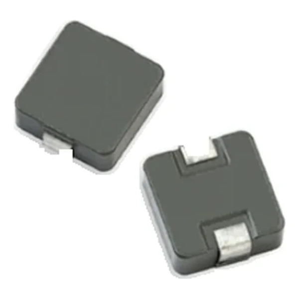
Eaton HCMA1104-3R3-R 3.3 uH Automotive High-Current Inductor
- Product Details
- Download
Eaton HCMA1104-3R3-R 3.3 uH Automotive High-Current Inductor
Specification Table
| Parameter | Value |
|---|---|
| Orderable part number | HCMA1104-3R3-R |
| OCL (open circuit inductance) | 3.3 uH ±20% |
| FLL minimum, at Isat | 1.85 uH |
| Irms (DC, 40 °C rise) | 10 A |
| Isat (20% rolloff @ +25 °C) | 16 A |
| DCR typical @ +20 °C | 10.8 mOhm |
| DCR maximum @ +20 °C | 11.8 mOhm |
| K-factor (Bp-p = K x L x dI) | 220, Bp-p in Gauss |
| Package | 11.5 x 10.3 mm |
| Height | 4.0 mm |
| Mounting | Surface mount |
| Operating temperature | -55 °C to +125 °C (ambient plus self-heating) |
| Qualification | AEC-Q200 |
| RoHS | Compliant, -R suffix |
| Data sheet | Eaton Technical Data 10349 |
Dimensions and Pad Layout

Drawing reproduced from Eaton Technical Data 10349: outline with
rated mm dimensions, recommended pad layout and winding schematic. Tolerances are stated on
the drawing itself.
How to Read These Ratings
AEC-Q200 qualified high-current inductor on a molded powder core, rated to +125 °C. The construction is chosen for current density: the winding is pressed into the magnetic material, so there is no bobbin wasting window area and the DCR stays low for the body size.
With 10.8 mOhm typical, the I-squared-R loss at the full 10 A rating is about 1.08 W. Compare that against the converter output power before deciding whether the part needs airflow or a copper pour under it.
The Isat column is 20% rolloff @ +25 °C. Note what it does and does not mean: it is a defined rolloff point, not a destruction limit. Above it the inductance continues to fall, which is why the transient peak current should be checked against the curve, not just against the number.
Energy storage at the saturation current is around 422 uJ, the number that connects the inductance and the current rating into a single transient figure.
K-factor 220 means the flux swing is about 726 Gauss per amp of ripple. Core loss scales with the flux amplitude and the frequency, so this is the number to carry into the loss calculation rather than the inductance alone.
Positioning in the Range
The HCMA family is the automotive high-current molded range, rated to +125 °C. It shares body sizes with the commercial HCM parts but is qualified and characterised for automotive use, with the current ratings to match the larger winding section.
Within the HCMA1104 family this is value 9 of 12, in a range that runs from 0.2 uH to 22 uH.
The next value up in the same family, HCMA1104-4R7-R, gives 4.7 uH at 8.5 A and DCR 17 mOhm: the extra inductance costs about 3.5 A of rated current.
- Core material: iron powder core, 11.5 x 10.3 mm body at 4.0 mm.
- Typical applications: body electronics; central body control module; vehicle access control system; headlamps, tai lamps and interior lighting; heating ventilation and air conditioning con- trollers (hvac); doors, window lift and seat control.
- Automotive derating practice: size against the saturation current at the hot corner and keep margin for the load transient, not just the steady-state current.
Putting It to Work
Copper resistance rises with temperature, so at the +125 °C limit the maximum DCR of 11.8 mOhm becomes roughly 16.7 mOhm. That is the figure to put into a hot-enclosure loss calculation; the +20 °C column is a bench number.
Design note: the AEC-Q200 grade covers the construction, not the thermal design of your board. The loss calculation is still the engineer’s job.
- Size the saturation margin at the maximum ambient the module will see.
- Check the current derating at the maximum ambient of the module.
- Confirm the terminal spacing against the rail voltage.
Frequently Asked Questions
What current can it carry continuously?
The Irms column, which is the DC current for the stated temperature rise without core loss. Continuous operation also depends on board copper and airflow, so the data sheet derating curves apply.
What current can it carry continuously?
The Irms column, which is the DC current for the stated temperature rise without core loss. Continuous operation also depends on board copper and airflow, so the data sheet derating curves apply.
What is the difference between Irms and Isat here?
Irms is the DC current for the rated temperature rise; Isat is the peak current at a defined inductance rolloff. A converter can exceed Irms briefly but must stay inside Isat.
Shenzhen Gaorunxin Technology Co., Ltd
Online message
Shenzhen Gaorunxin Technology Co., Ltd