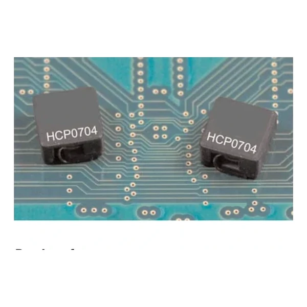
Eaton HCP0704-1R8-R Iron Powder Inductor 1.80 uH, Isat 13 A
- Product Details
- Download
Eaton HCP0704-1R8-R Iron Powder Inductor 1.80 uH, Isat 13 A
Key Specifications
| Parameter | Value |
|---|---|
| Orderable part number | HCP0704-1R8-R |
| OCL (open circuit inductance) | 1.80 uH ±25% |
| FLL minimum, at Isat | 1.26 uH |
| Irms (DC, 40 °C rise) | 8.5 A |
| Isat (20% rolloff @ +25 °C) | 13 A |
| DCR typical @ +20 °C | 11 mOhm |
| K-factor (Bp-p = K x L x dI) | 203, Bp-p in Gauss |
| Package | 6.8 x 6.8 mm |
| Height | 4.2 mm |
| Mounting | Surface mount |
| Operating temperature | -40 °C to +155 °C (ambient plus self-heating) |
| Qualification | Commercial grade |
| RoHS | Compliant, -R suffix |
| Data sheet | Eaton Technical Data 4348 |
Mechanical Drawing

Drawing reproduced from Eaton Technical Data 4348: outline with
rated mm dimensions, recommended pad layout and winding schematic. Tolerances are stated on
the drawing itself.
The Figures Explained
This part trades inductance per unit volume for current handling: iron powder saturates at a much higher flux density than ferrite, and the soft curve means the converter still has inductance at peak current. Standard choice for multiphase buck stages and battery power systems.
Copper loss at the rated current works out to roughly 0.795 W from a typical DCR of 11 mOhm at 8.5 A. It is the number to start a thermal stack-up with, before core loss and before AC resistance rise.
The saturation rating reads 20% rolloff @ +25 °C. Treat it as the edge of the linear region: below it the inductance is within tolerance, above it the value droops. For a current-mode converter that means the peak current at the worst-case load step is what must fit under this number.
Stored energy at Isat is about 152 uJ, which is the energy the inductor hands to the load during a transient before the control loop reacts.
With K = 203, a peak-to-peak ripple of one amp produces roughly 365 Gauss of flux swing. Read the core-loss graph at that amplitude and at the switching frequency to get the core contribution to the total loss.
What This Family Is For
The HCP family is the iron powder, shielded, high-current range for VRM and point-of-load work. It covers modest inductance values at high DC bias, with the soft saturation curve that iron powder is chosen for.
Of the 7 values listed for HCP0704, this is the 4th, in a family covering 0.4 uH to 4.7 uH.
One step down the table, HCP0704-1R0-R, sits at 1.00 uH with 12 A and 6.2 mOhm – the lower inductance buys about 4.5 A of extra current in the same body.
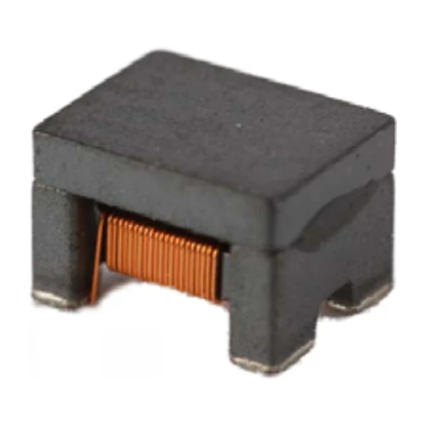
- Core material: iron powder core, 6.8 x 6.8 mm body at 4.2 mm.
- Typical applications: voltage regulator module (vrm); multi-phase regulators; desktop and servers; base station equipment; notebook and laptop regulators; data networking and storage systems.
- Iron powder has a soft saturation curve but a lower permeability than ferrite, so the turns count – and therefore the DCR – is higher for the same inductance.
Design Notes
Copper resistance rises with temperature, so at the +155 °C limit the maximum DCR of 11 mOhm becomes roughly 16.8 mOhm. That is the figure to put into a hot-enclosure loss calculation; the +20 °C column is a bench number.
Design note: at high DC bias the inductance is well below OCL. Use the inductance-versus-current curve for the ripple calculation, not the headline value.
- Check the inductance at the operating bias, not the catalogue value.
- Account for the lower permeability of iron powder in the turns count and DCR.
- Account for the lower permeability of iron powder in the turns count and DCR.
Frequently Asked Questions
What core loss should I expect?
Read the core-loss curve at the flux amplitude implied by the K-factor and the ripple, at the switching frequency. Core loss is quoted per unit volume, so compare curves rather than single numbers.
Is the saturation curve linear?
No – it is deliberately soft. Inductance droops progressively above the rated current, which is why the ripple calculation should use the inductance at the actual bias, not the headline value.
Is the saturation curve linear?
No – it is deliberately soft. Inductance droops progressively above the rated current, which is why the ripple calculation should use the inductance at the actual bias, not the headline value.
Shenzhen Gaorunxin Technology Co., Ltd
Online message
Shenzhen Gaorunxin Technology Co., Ltd