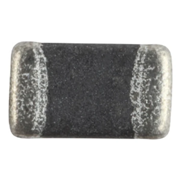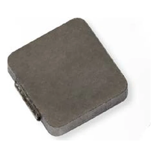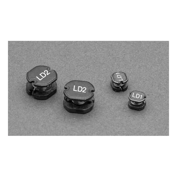
Eaton LD1-3R9-R 3.9 uH Metalized Inductor, Isat 2.14 A
- Product Details
- Download
Eaton LD1-3R9-R 3.9 uH Metalized Inductor, Isat 2.14 A
Electrical Specifications
| Parameter | Value |
|---|---|
| Orderable part number | LD1-3R9-R |
| Inductance | 3.9 uH ±20% |
| DCR maximum @ +25 °C | 76 mOhm |
| Irms (DC, 40 °C rise) | 1.75 A |
| Isat | 2.14 A |
| Mounting | Through-hole |
| Operating temperature | -40 °C to +125 °C |
| Qualification | Commercial grade |
| RoHS | Compliant, -R suffix |
| Data sheet | Eaton Technical Data 4310 |
Outline Drawing

Drawing reproduced from Eaton Technical Data 4310: outline with rated mm dimensions, pad layout and marking. Tolerances are stated on the drawing.
What the Numbers Mean
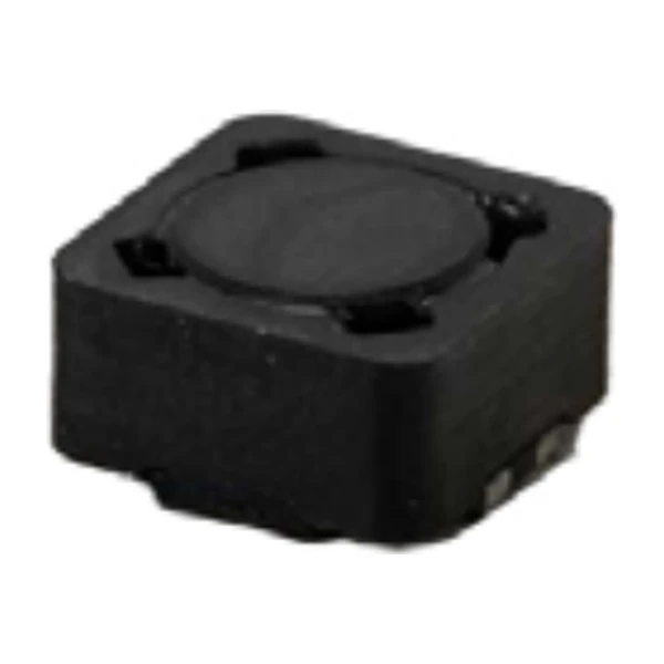
The drum geometry concentrates the field in the core but leaves the ends open, so the inductance depends on the surroundings more than a shielded part would. That is acceptable in the applications these parts serve – filters, bias supplies, low current DC-DC stages – where the board is not densely packed.
At 1.75 A the winding dissipates about 0.233 W in copper, using the 76 mOhm figure. That is the DC floor of the loss budget: ripple and core loss come on top of it.
Saturation is reached at 2.14 A. Beyond that point the inductance falls on the soft part of the curve, and the converter’s ripple grows faster than the load current does.
Within the LD1 family this is value 7 of 27, in a range that runs from 1 to 330 uH.
Positioning in the Range
The drum core family covers about 1 µH to tens of microhenry in axial, radial and surface-mount bodies. It is the value range between the chip inductors and the large toroids.
- The open magnetic path means nearby metal changes the inductance. Keep the specified clearance to shields and screws.
- Typical applications: buck or boost inductor; noise filtering and output filter chokes; computers; power supplies; test equipment instrumentation smd device.
- Design note: the value tolerance is wide by design; do not build a resonant circuit around the nominal inductance without checking the band.
Frequently Asked Questions
What is the rated current based on?
A defined temperature rise from DC current. At higher ambient the thermal margin shrinks, so derate against the actual board temperature.
Can it be used in a switching converter?
Yes, within its current and frequency range. Check the core loss at the switching frequency before assuming the DC rating is the limit.
Can it be used in a switching converter?
Yes, within its current and frequency range. Check the core loss at the switching frequency before assuming the DC rating is the limit.
Shenzhen Gaorunxin Technology Co., Ltd
Online message
Shenzhen Gaorunxin Technology Co., Ltd