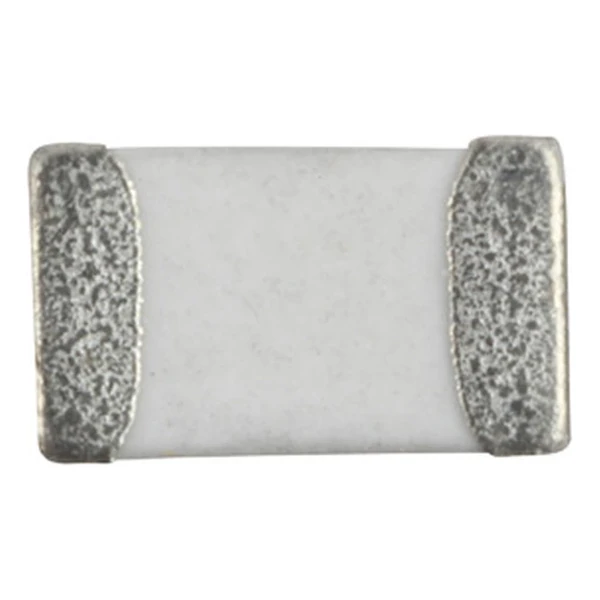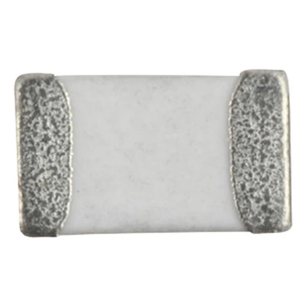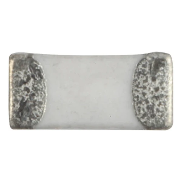
Eaton MCL1608V2-181-R 180.0 nH SMD Inductor, SRF 8 MHz
- Product Details
- Download
Eaton MCL1608V2-181-R 180.0 nH SMD Inductor, SRF 8 MHz
Key Specifications
| Parameter | Value |
|---|---|
| Orderable part number | MCL1608V2-181-R |
| Inductance | 180.0 nH 200 |
| Q minimum | 100 |
| DCR maximum @ +25 °C | 400000 mOhm |
| Rated current maximum | 2 mA |
| SRF minimum | 8 MHz |
| Test frequency | 50 MHz |
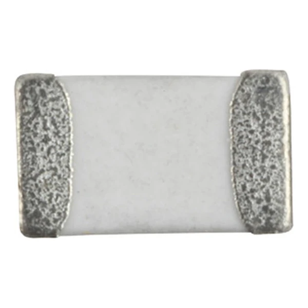
| Package | 1.6 x 0.8 mm |
| Size code | 1608 (0603) |
| Mounting | Surface mount |
| Operating temperature | -40 °C to +85 °C |
| Qualification | Commercial grade |
| RoHS | Compliant, -R suffix |
| Data sheet | Eaton Technical Data 10927 |
Mechanical Dimensions & Pad Layout

Drawing reproduced from Eaton Technical Data 10927: outline with rated mm dimensions, pad layout and marking. Tolerances are stated on the drawing.
How to Read These Ratings
The inductance here is a few nanohenry, which puts the part in RF and high-speed digital territory: matching networks, filter sections, bias chokes on amplifier supplies, and the small isolation inductors that keep clock harmonics out of connectors. The multilayer body keeps the parasitics predictable, and the Q column tells you how much loss the part adds at the test frequency.
The row reads 180.0 nH 200 with a minimum Q of 100 at 50 MHz. Q is the ratio of reactance to resistance at that frequency, so a Q of 100 means the part’s loss is about 1 % of its reactance in that band.
Self-resonance is quoted as 8 MHz minimum. Below it the part is inductive; above it the inter-layer capacitance takes over. The margin between the operating band and 8 MHz is the design headroom.
Within the MCL1608V2 family this is value 28 of 34, in a range that runs from 0.001 to 0.47 nH.
What This Family Is For
The multilayer chip family covers nanohenry to a few microhenry values in 0402 through 1812 bodies. It is the range where the inductance is too small for a wound part to be practical and where the self-resonant frequency sets the usable band.
- The rated current is a thermal limit for the part in free air, not a saturation limit. At high ambient the current has to be derated.
- Typical applications: industrial connectivity (iot); wireless communiations; bluetooth; wifi; antenna.
- Design note: compare SRF against the highest frequency the circuit will see, not just the fundamental.
Frequently Asked Questions
Can I replace a wire-wound chip with this part?
Only if the Q and the current rating suit the circuit. Multilayer parts have lower Q and lower current capability than wire-wound parts of the same size.
Can I replace a wire-wound chip with this part?
Only if the Q and the current rating suit the circuit. Multilayer parts have lower Q and lower current capability than wire-wound parts of the same size.
Why is the inductance quoted at a test frequency?
At nanohenry values the parasitic capacitance and the measurement fixture both matter. The value is only meaningful at the frequency stated, and the Q column tells you how much of the reactance is loss at that point.
Shenzhen Gaorunxin Technology Co., Ltd
Online message
Shenzhen Gaorunxin Technology Co., Ltd