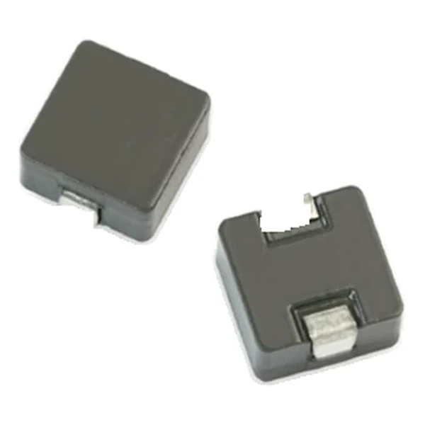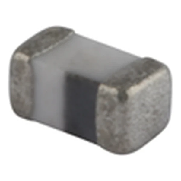
Eaton MCLA1005V2-150-R 15.0 nH Chip Inductor 0402
- Product Details
- Download
Eaton MCLA1005V2-150-R 15.0 nH Chip Inductor 0402
Electrical Specifications
| Parameter | Value |
|---|---|
| Orderable part number | MCLA1005V2-150-R |
| Inductance | 15.0 nH ±5% |
| Q minimum | 8 |
| DCR maximum @ +25 °C | 500 mOhm |
| Rated current maximum | 300 mA |
| SRF minimum | 2300 MHz |
| Test frequency | 100 MHz |
| Test voltage | 50 mV |
| Package | 1.0 x 0.5 mm |
| Size code | 1005 (0402) |
| Mounting | Surface mount |
| Operating temperature | -40 °C to +125 °C |
| Qualification | AEC-Q200 |
| RoHS | Compliant, -R suffix |
| Data sheet | Eaton Technical Data 10974 |
Mechanical Drawing

Drawing reproduced from Eaton Technical Data 10974: outline with rated mm dimensions, pad layout and marking. Tolerances are stated on the drawing.
How to Read These Ratings
A multilayer chip inductor is a coil printed in layers of ceramic and metal, fired into a single body. There is no winding to buzz or shift, the inductance is set by the printed pattern, and the part sits on the board like any other 0402 or 0603 component. That construction is why these parts are used wherever the value is small and the quantity is large.
The row reads 15.0 nH ±5% with a minimum Q of 8 at 100 MHz. Q is the ratio of reactance to resistance at that frequency, so a Q of 8 means the part’s loss is about 12.5 % of its reactance in that band.
Self-resonance is quoted as 2300 MHz minimum. Below it the part is inductive; above it the inter-layer capacitance takes over. The margin between the operating band and 2300 MHz is the design headroom.
Within the MCLA1005V2 family this is value 27 of 45, in a range that runs from 0.001 to 0.33 nH.
What This Family Is For
The multilayer chip family covers nanohenry to a few microhenry values in 0402 through 1812 bodies. It is the range where the inductance is too small for a wound part to be practical and where the self-resonant frequency sets the usable band.
- The rated current is a thermal limit for the part in free air, not a saturation limit. At high ambient the current has to be derated.
- Typical applications: adas; infotainment; wireless communications; wifi, bluetooth, satellite; antennas tuning.
- Design note: compare SRF against the highest frequency the circuit will see, not just the fundamental.
Frequently Asked Questions
Why is the inductance quoted at a test frequency?
At nanohenry values the parasitic capacitance and the measurement fixture both matter. The value is only meaningful at the frequency stated, and the Q column tells you how much of the reactance is loss at that point.
Can I replace a wire-wound chip with this part?
Only if the Q and the current rating suit the circuit. Multilayer parts have lower Q and lower current capability than wire-wound parts of the same size.
Can I replace a wire-wound chip with this part?
Only if the Q and the current rating suit the circuit. Multilayer parts have lower Q and lower current capability than wire-wound parts of the same size.
Shenzhen Gaorunxin Technology Co., Ltd
Online message
Shenzhen Gaorunxin Technology Co., Ltd