Eaton MLVC08V024C170 24 V Multilayer Varistor
- Product Details
- Download
Eaton MLVC08V024C170 24 V Multilayer Varistor
Electrical Specifications
| Parameter | Value |
|---|---|
| Orderable part number | MLVC08V024C170 |
| Working voltage, DC | 24 Vdc |
| Working voltage, AC | 17 Vac |
| Varistor voltage at 1 mA | 33 V ±10% |
| Clamping voltage at 1 A | 58 V |
| Energy absorption, 10/1000 us | 0.1 J |
| Peak current, 8/20 us | 35 A |
| Typical capacitance at 1 MHz | 170 pF |
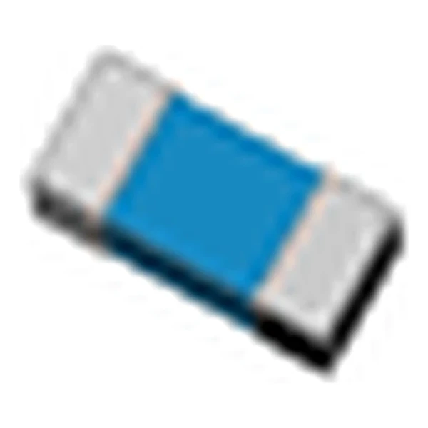
| Package | 0805 (2012 metric) |
| Mounting | Surface mount |
| Operating temperature | -55 °C to +125 °C |
| Qualification | Commercial grade |
| RoHS | Compliant, halogen free |
| Data sheet | Eaton Technical Data 11237 |
Dimensions, recommended pad or hole pattern and the derating curves are
on the data sheet pages; the package line above gives the body size as Eaton states it.
What the Numbers Mean
These parts are zinc oxide ceramics sintered into a chip, so the response is faster than a junction device and there is no wear-out mechanism below the rated energy. What does degrade them is repeated energy above the rating, which shows up as a falling varistor voltage.
The clamp column works out at 1.76 times the varistor voltage: 58 V at the rated current against 33 V at 1 mA. That ratio is what the downstream part has to survive, not the 33 V figure on the label.
The 170 pF typical capacitance is the cost of the clamp. On a power rail it is irrelevant; on a data line it is the reason to look at the low-capacitance versions of the same voltage.
Within the MLVC general type family this is item 19 of 41 in the Eaton catalogue.
Where This Series Fits
The part goes across the line it protects, as close to the connector or the cable entry as the layout allows. Lead length matters: every extra millimetre of trace between the connector and the varistor adds inductance and raises the voltage the protected chip actually sees.
- The energy rating assumes a single pulse. Repeating the same transient heats the body faster than the datasheet curve suggests, because the curve is drawn for one event at a time.
- The response time is quoted below a nanosecond because the ceramic turns conductive in the grain boundaries, not because of a junction.
Frequently Asked Questions
How many ESD strikes can it take?
The ESD rating is a qualification level, not a lifetime count. IEC 61000-4-2 level 4 is 8 kV contact and 15 kV air, and the part is expected to survive repeated strikes at that level because the energy per strike is small.
Does the clamp voltage scale with the surge current?
Yes. The clamp column is quoted at a stated current, usually 1 A. At ten times that current the residual voltage is higher, so read the V-I curve rather than the single number when the surge is large.
Why is the DC rating lower than the AC rating on some parts?
It is not, on these: the AC rating is an RMS value, so the DC rating is set at the peak of that sine plus margin. Where the two look inconsistent, check which one is quoted as RMS.
Shenzhen Gaorunxin Technology Co., Ltd
Online message
Shenzhen Gaorunxin Technology Co., Ltd