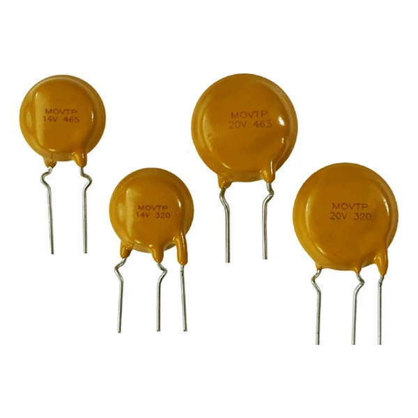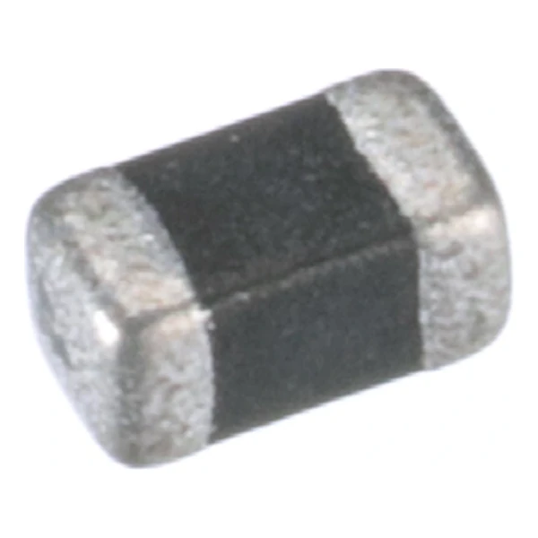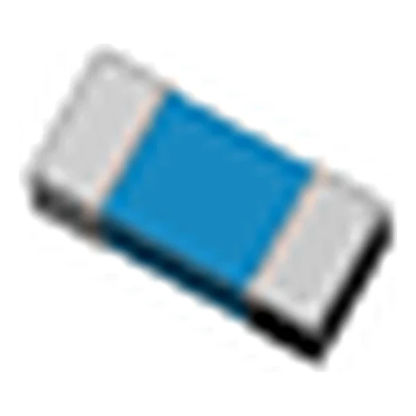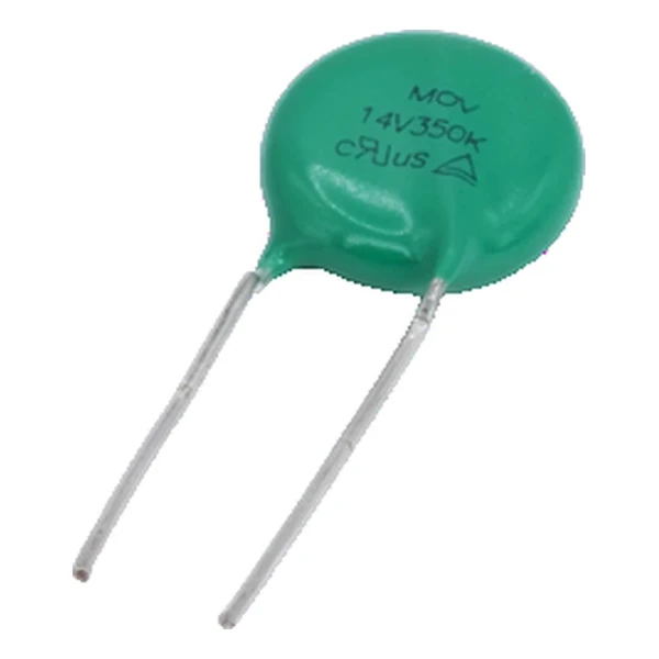
Eaton MLVC32V045C1500 3225 Chip Varistor 45 Vdc
- Product Details
- Download
Eaton MLVC32V045C1500 3225 Chip Varistor 45 Vdc
Specification Table
| Parameter | Value |
|---|---|
| Orderable part number | MLVC32V045C1500 |
| Working voltage, DC | 45 Vdc |
| Working voltage, AC | 35 Vac |
| Varistor voltage at 1 mA | 56 V ±10% |
| Clamping voltage at 1 A | 99 V |
| Energy absorption, 10/1000 us | 1.1 J |
| Peak current, 8/20 us | 100 A |
| Typical capacitance at 1 MHz | 1500 pF |
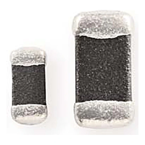
| Package | 3225 (8063 metric) |
| Mounting | Surface mount |
| Operating temperature | -55 °C to +125 °C |
| Qualification | Commercial grade |
| RoHS | Compliant, halogen free |
| Data sheet | Eaton Technical Data 11236 |
Dimensions, recommended pad or hole pattern and the derating curves are
on the data sheet pages; the package line above gives the body size as Eaton states it.
Reading the Data Sheet
In a multilayer construction the zinc oxide grains are stacked in many thin layers, so the same body height gives a higher voltage per unit area than a single-layer disc. That is how an 0402 chip reaches 18 Vdc working voltage without becoming thick.
The clamp column works out at 1.77 times the varistor voltage: 99 V at the rated current against 56 V at 1 mA. That ratio is what the downstream part has to survive, not the 56 V figure on the label.
The 1500 pF typical capacitance is the cost of the clamp. On a power rail it is irrelevant; on a data line it is the reason to look at the low-capacitance versions of the same voltage.
Within the MLVC high energy family this is item 72 of 97 in the Eaton catalogue.
Positioning in the Range
The return path is half the component. A varistor tied to a ground plane far from the connector leaves the loop inductance in series with the clamp, and the residual voltage at the chip is the clamp plus L di/dt.
- Do not use a varistor as a series element or in a signal path carrying DC. It is a shunt device, and any steady current through it is a fault.
- The response time is quoted below a nanosecond because the ceramic turns conductive in the grain boundaries, not because of a junction.
Frequently Asked Questions
Does the package size change the electrical ratings?
Yes, the energy and peak current scale with the body volume, so a 0402 and a 1206 of the same voltage are not interchangeable on a surge.
Is the varistor voltage the same as the working voltage?
No. The working voltage is the continuous DC or AC level the part can sit at; the varistor voltage is measured at 1 mA and is typically 1.5 to 2 times higher. Sizing on the varistor voltage would put the part into conduction on a normal rail.
What does the capacitance do to my signal?
It loads the line. At 1 MHz a 100 pF part is about 1.6 kOhm of reactance, which is harmless on a power rail and fatal on a 480 Mbit USB pair. Choose a low-capacitance version when the line carries data.
Shenzhen Gaorunxin Technology Co., Ltd
Online message
Shenzhen Gaorunxin Technology Co., Ltd