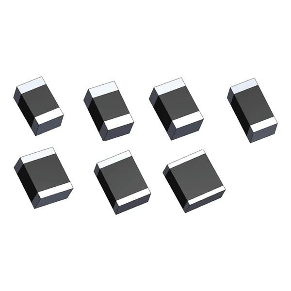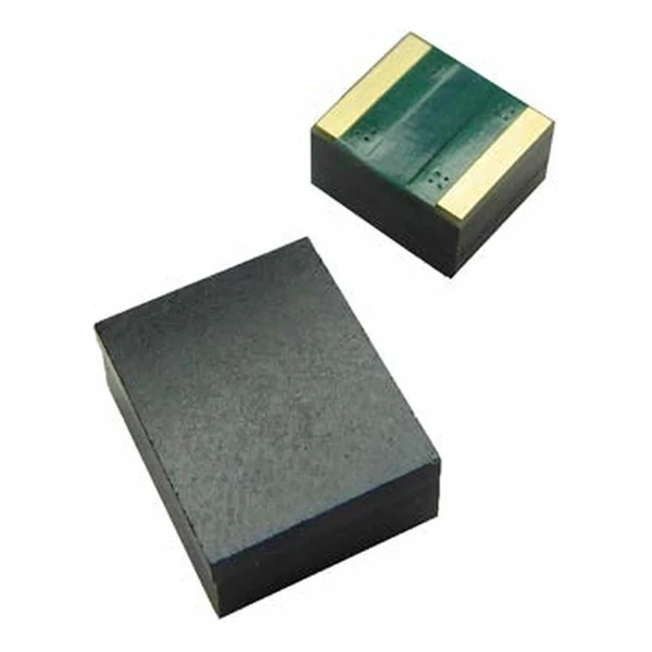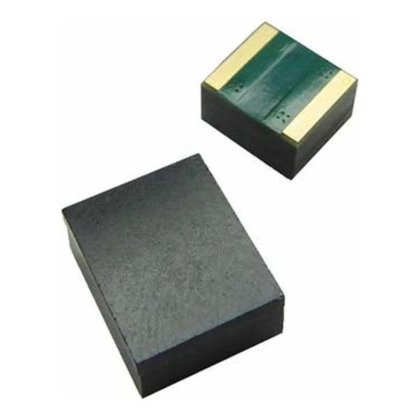
Eaton MOVS4032V040 Surface Mount MOV 4032
- Product Details
- Download
Eaton MOVS4032V040 Surface Mount MOV 4032
Ratings at a Glance
| Parameter | Value |
|---|---|
| Orderable part number | MOVS4032V040 |
| Working voltage, RMS | 40 Vrms |
| Working voltage, DC | 56 Vdc |
| Varistor voltage at 1 mA | 61.2-74.8 V |
| Leakage current at 0.8 Vv | max. 50 uA |
| Clamping voltage, 8/20 us | 145 V at 2.5 A |
| Peak current, 8/20 us | 250 A |
| Maximum energy, 10/1000 us | 4.2 J |
| Package | 4032 |
| Mounting | Surface mount |
| Operating temperature | -40 °C to +85 °C |
| Qualification | Commercial grade |
| RoHS | Compliant, halogen free |
| Data sheet | Eaton Technical Data ELX1004 |
Dimensions, recommended pad or hole pattern and the derating curves are
on the data sheet pages; the package line above gives the body size as Eaton states it.
The Figures Explained
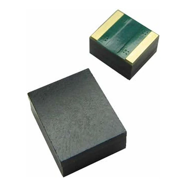
The thickness column is the one that gets overlooked. A 4032 varistor is a 3.2 mm to 5.6 mm tall block, and that height has to clear the enclosure or the board-to-board gap before the part is designed in.
The clamp column works out at 2.37 times the varistor voltage: 145 V at the rated current against 61.2~74.8 V at 1 mA. That ratio is what the downstream part has to survive, not the 61.2~74.8 V figure on the label.
Standing at 56 V the leakage is at most 50 uA, which is 2.8 mW of continuous dissipation. Small, but it is why a varistor on a battery rail has to be chosen on leakage and not only on voltage.
At – mm tall this is the part that has to fit under the enclosure. The 4.2 J rating and the 250 A peak come from a body that size, so a lower profile in the same footprint would mean less energy.
Within the MOVS4032 family this is item 8 of 30 in the Eaton catalogue.
Series Positioning
Place the chip directly across the connector pins with the ground return on the same layer. The part protects what is between its own terminals, so a shared ground path back to the connector defeats it.
- The chip has no lead frame to spread heat, so the rated power assumes the recommended pad. A reduced pad raises the body temperature at the same continuous current.
- Reflow profile and pad geometry are in the data sheet; the part is not sensitive to moisture at the levels of a plastic package, but the solder joint is the thermal path.
Frequently Asked Questions
Can two parts be paralleled for more energy?
Only if they are matched, which they are not. The varistor voltage tolerance means one part takes most of the current, so the pair behaves like the weaker one plus a little.
What is the operating temperature range?
The table states it for each family; the upper limit is the point where the rated power falls to zero, not the point where the part stops working.
Is the part halogen free?
Yes, the data sheet states halogen free and RoHS compliance without exemptions for the whole family.
Shenzhen Gaorunxin Technology Co., Ltd
Online message
Shenzhen Gaorunxin Technology Co., Ltd