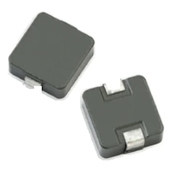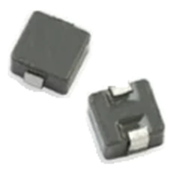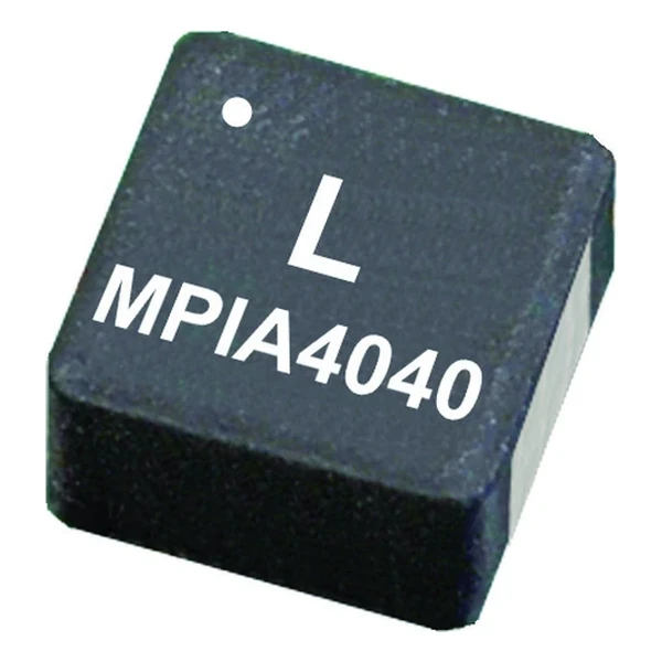
Eaton MPIA4040R1-1R0-R 1 uH AEC-Q200 Inductor 40 mOhm
- Product Details
- Download
Eaton MPIA4040R1-1R0-R 1 uH AEC-Q200 Inductor 40 mOhm
Electrical Specifications
| Parameter | Value |
|---|---|
| Orderable part number | MPIA4040R1-1R0-R |
| Inductance | 1 uH |
| DCR typical @ +20 °C | 40 mOhm |
| Irms (DC, 40 °C rise) | 3.7 A |
| Isat | 7.7 A |
| K-factor | 990 |
| Mounting | Surface mount |
| Operating temperature | -55 °C to +125 °C |
| Qualification | AEC-Q200 |
| RoHS | Compliant, -R suffix |
| Data sheet | Eaton Technical Data 10230 |
Dimensions and Pad Layout

Drawing reproduced from Eaton Technical Data 10230: outline with
rated mm dimensions, pad layout and marking.
How to Read These Ratings
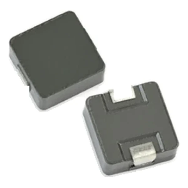
A molded automotive power inductor with a soft saturation curve: as current rises the inductance droops instead of collapsing, so a converter keeps control through a load step. The body is molded around the winding, which contains the field.
At 3.7 A the winding dissipates about 0.548 W in copper using the typical DCR of 40 mOhm. That is the DC floor of the loss budget – ripple and core loss come on top.
The core stores about 29.6 uJ at the saturation point, which is the energy available to bridge a load step.
The K-factor of 990 converts inductance and ripple into flux swing; read the core-loss curve at that amplitude.
Within the MPIA4040R1 family this is value 7 of 11, in a range from 0.09 uH to 4.7 uH.
What This Family Is For
The MPIA family is the automotive miniature power range: AEC-Q200 qualified, low profile, in sizes from 2 mm to 4 mm, with both typical and maximum DCR quoted for every row.
- DCR is quoted at +20 °C; copper rises about 0.4 % per °C, so the hot loss is higher than the cold figure.
- Typical applications: body electronics – central body control module – vehicle access control system – headlamps, tail lamps and interior lighting – door control; chassis and safety electronics – airbag control unit.
- Design note: ripple from OCL, thermal from Irms, transient from Isat. Three numbers, three checks.
Frequently Asked Questions
What is the difference between Irms and Isat?
Irms is the DC current for the rated temperature rise; Isat is the peak current at a defined inductance rolloff. A converter can exceed Irms briefly but must stay inside Isat.
Is the part shielded?
The molded body encloses the winding, so the external field is small enough for dense layouts.
Why two DCR columns?
Typical and maximum. A guaranteed thermal design uses the maximum; a nominal efficiency calculation can use the typical.
Shenzhen Gaorunxin Technology Co., Ltd
Online message
Shenzhen Gaorunxin Technology Co., Ltd