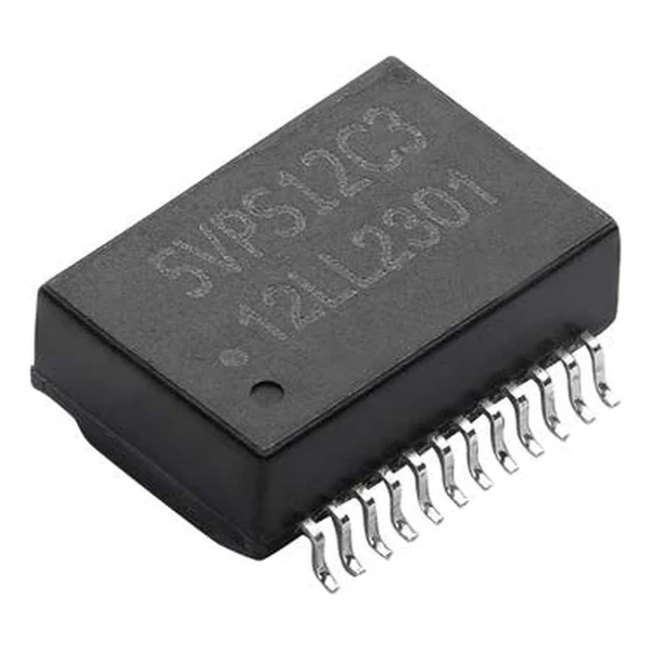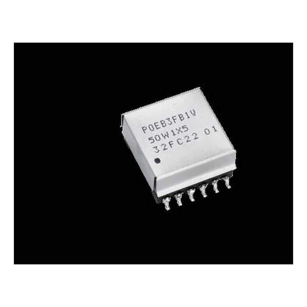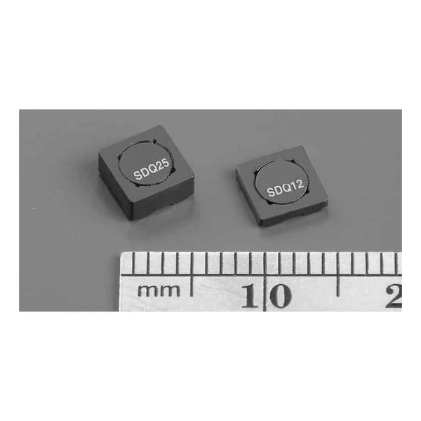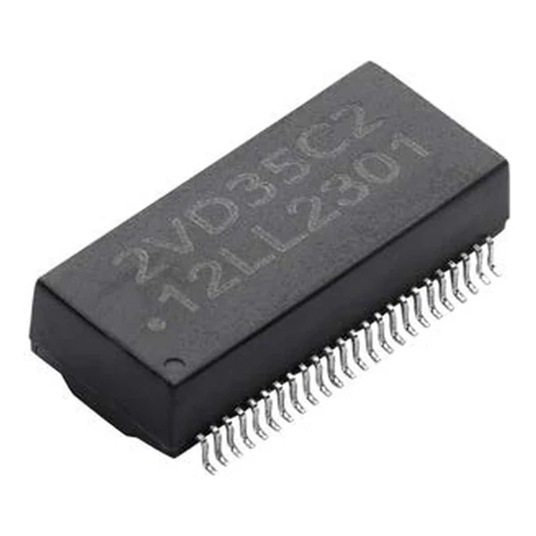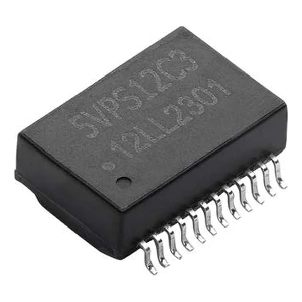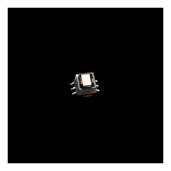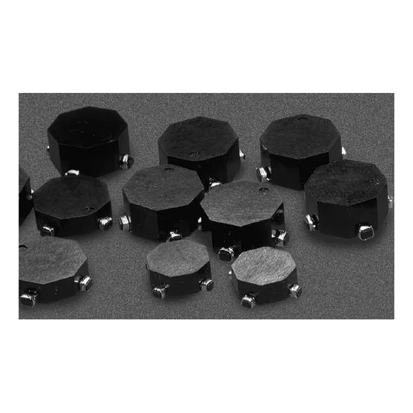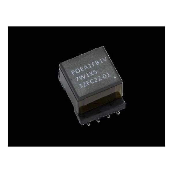
Eaton POEA1FB1V7W1X12 PoE PD Transformer 7 W
- Product Details
- Download
Eaton POEA1FB1V7W1X12 PoE PD Transformer 7 W
Specification Table
| Parameter | Value |
|---|---|
| Orderable part number | POEA1FB1V7W1X12 |
| Output power | 7 W |
| OCL (primary inductance) | 155 uH |
| SCL (saturated inductance) | 3.25 uH |
| Isat | 0.75 A |
| Turns ratio pri : sec : aux | 1:0.667:0.667 |
| Output configuration | (1) x 12.0 V @ 0.6 A |
| DCR primary | 414 mOhm |
| DCR secondary 1 | 343 mOhm |
| DCR secondary 2 | not fitted |
| DCR auxiliary | 822 mOhm |
| Schematic variant | Winding arrangement 3 |
| Package | 15.2 x 12.5 x 11.6 mm |
| Mounting | Surface mount |
| Operating temperature | -40 C to +125 C |
| Qualification | Commercial grade |
| RoHS | Compliant, -R suffix |
| Data sheet | Eaton Technical Data ELX1266 |
Outline drawing, winding arrangement and recommended pad layout are on
page 2 of Eaton Technical Data ELX1266; the package line above gives the body size where
the data sheet states it.
Reading the Data Sheet
This is a flyback transformer for Power over Ethernet powered devices: primary, secondary and an auxiliary winding for the controller supply, all on one bobbin with reinforced insulation between primary and secondary.
At the 0.75 A saturation point the primary stores about 43.6 uJ, which sets the maximum energy per switching cycle.
Within the POEA1FB1V7W1X12 family this is item 1 of 1 in the Eaton catalogue.
Positioning in the Range
The PoE range covers 3 W to 156 W of output in EFD15 to EPC46 cores, flyback and forward topologies, with schematic variants for the common controller families.
- The isolation barrier is only as good as the board spacing around it. Check creepage on the footprint, not just the part rating.
- Typical applications: lighting; industrial automation; security systems; voip phone systems; network and bluetooth access points.
- Design note: check Isat at the maximum ambient, and remember that the auxiliary winding also carries current.
Frequently Asked Questions
Can I use a forward part in a flyback design?
No. The two topologies need different turns ratios and different primary inductance, and a forward transformer has no gap for energy storage.
Can I use a forward part in a flyback design?
No. The two topologies need different turns ratios and different primary inductance, and a forward transformer has no gap for energy storage.
Can I use a forward part in a flyback design?
No. The two topologies need different turns ratios and different primary inductance, and a forward transformer has no gap for energy storage.
Shenzhen Gaorunxin Technology Co., Ltd
Online message
Shenzhen Gaorunxin Technology Co., Ltd