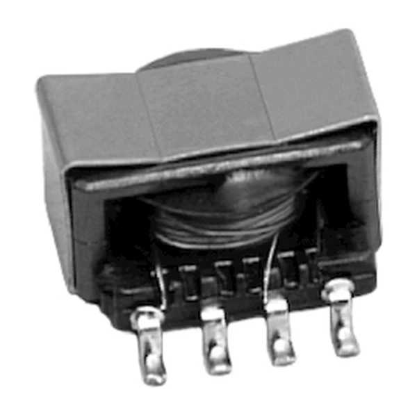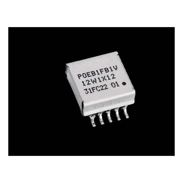
Eaton POEB1FB1V12W1X12 PoE PD Transformer 12 W
- Product Details
- Download
Eaton POEB1FB1V12W1X12 PoE PD Transformer 12 W
Key Specifications
| Parameter | Value |
|---|---|
| Orderable part number | POEB1FB1V12W1X12 |
| Output power | 12 W |
| OCL (primary inductance) | 140 uH |
| SCL (saturated inductance) | 1.3 uH |
| Isat | 1 A |
| Turns ratio pri : sec : aux | 1:0.389:0.444 |
| Output configuration | (1) x 12.0 V @ 1.0 A |
| DCR primary | 365 mOhm |
| DCR secondary 1 | 40 mOhm |
| DCR secondary 2 | not fitted |
| DCR auxiliary | 200 mOhm |
| Schematic variant | Winding arrangement 1 |
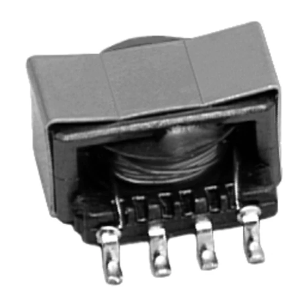
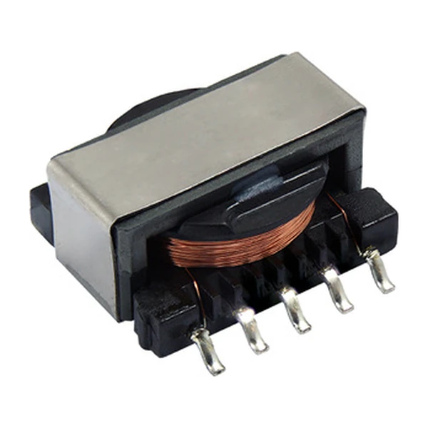
| Package | 22.3 x 17.3 x 9 mm |
| Mounting | Surface mount |
| Operating temperature | -40 C to +125 C |
| Qualification | Commercial grade |
| RoHS | Compliant, -R suffix |
| Data sheet | Eaton Technical Data ELX1268 |
Outline drawing, winding arrangement and recommended pad layout are on
page 2 of Eaton Technical Data ELX1268; the package line above gives the body size where
the data sheet states it.
How to Read These Ratings
A PoE PD flyback transformer takes the 37 to 57 V on the cable and steps it down to the rails the powered device needs, with the isolation barrier in between. The turns ratio, the primary inductance and the saturation current are set by the controller and the power level, not chosen freely.
At the 1 A saturation point the primary stores about 70 uJ, which sets the maximum energy per switching cycle.
Within the POEB1FB1V12W1X12 family this is item 1 of 1 in the Eaton catalogue.
Where This Series Fits
The PoE range covers 3 W to 156 W of output in EFD15 to EPC46 cores, flyback and forward topologies, with schematic variants for the common controller families.
- The isolation barrier is only as good as the board spacing around it. Check creepage on the footprint, not just the part rating.
- Typical applications: lighting; industrial automation; security systems; voip phone systems; network and bluetooth access points.
- Design note: check Isat at the maximum ambient, and remember that the auxiliary winding also carries current.
Frequently Asked Questions
What does the schematic number mean?
It refers to the winding arrangement drawing in the data sheet: which winding is primary, how many secondaries, and where the auxiliary sits. Two parts with the same power level and different schematic numbers are not interchangeable.
Can I use a forward part in a flyback design?
No. The two topologies need different turns ratios and different primary inductance, and a forward transformer has no gap for energy storage.
Why is SCL quoted as well as OCL?
OCL is the open-circuit inductance and SCL is the saturated value. The controller needs OCL to set the current ramp and SCL to know where the core runs out, and the gap between them is the usable current range.
Shenzhen Gaorunxin Technology Co., Ltd
Online message
Shenzhen Gaorunxin Technology Co., Ltd