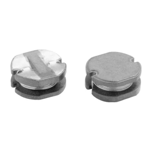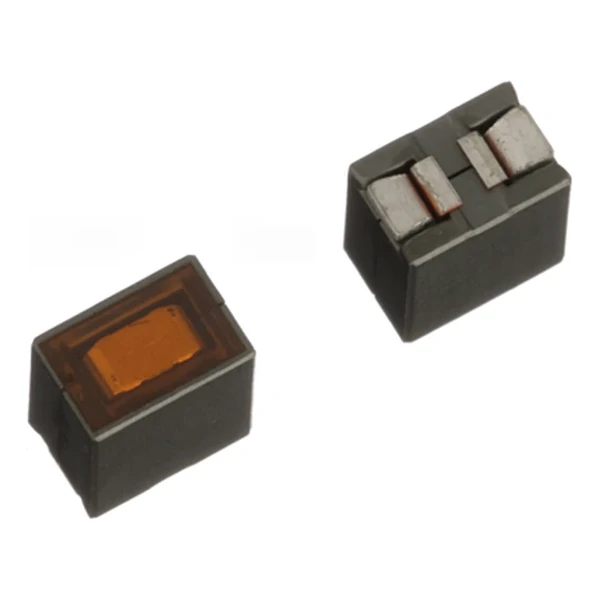
Eaton TL1012V2-R100-R 100 nH TLVR Power Inductor
- Product Details
- Download
Eaton TL1012V2-R100-R 100 nH TLVR Power Inductor
Electrical Specifications
| Parameter | Value |
|---|---|
| Orderable part number | TL1012V2-R100-R |
| Primary inductance Lpri (terminals 3-4) | 100 nH ±10% |
| Secondary inductance Lsec (terminals 1-2) | 100 nH ±10% |
| FLL minimum at Isat1 | 72 nH |
| DCR primary @ +20 °C | 0.37 mOhm |
| DCR secondary @ +20 °C | 0.125 mOhm |
| Irms secondary (40 °C rise) | 75 A |
| Isat1 (20 % rolloff @ +25 °C) | 110 A |
| Isat2 (20 % rolloff @ +100 °C) | 95 A |
| Isat3 (20 % rolloff @ +125 °C) | 88 A |
| K-factor (Bp-p = K x L x dI x 10^-3) | 360 |
| Coupling coefficient Kps | 0.94 |
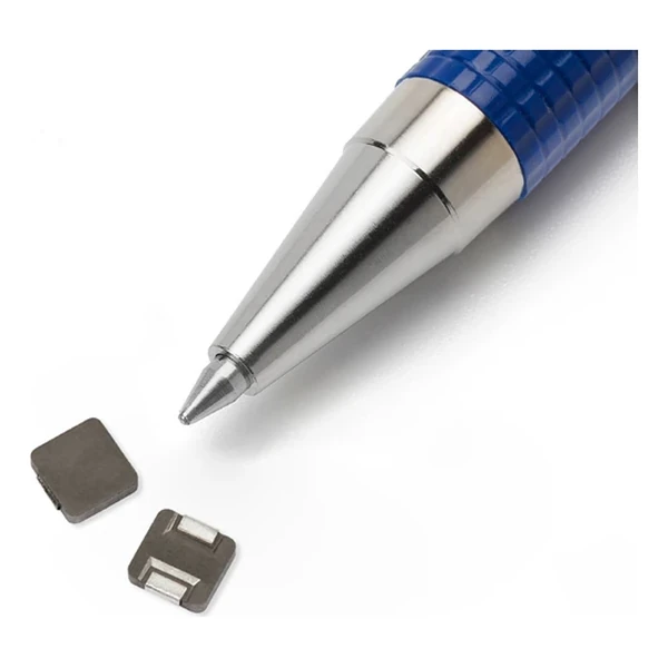
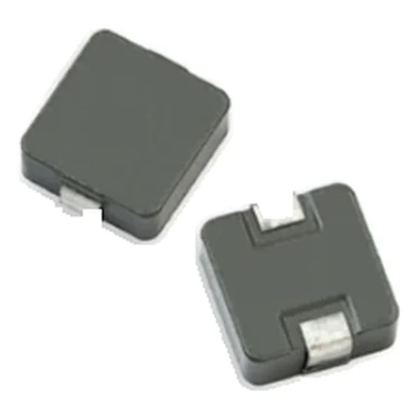
| Package | 10.0 x 6.0 mm, 12.0 mm high |
| Mounting | Surface mount |
| Operating temperature | -40 °C to +125 °C |
| Qualification | Commercial grade |
| RoHS | Compliant, -R suffix |
| Data sheet | Eaton Technical Data ELX1155 |
Dimensions and Pad Layout

Drawing reproduced from Eaton Technical Data ELX1155: outline views
with rated mm dimensions, pad layout and marking.
What the Numbers Mean
Three numbers describe this part and they are not interchangeable. Lpri is what the phase sees; Lsec is the winding that forms the shared loop; FLL is the inductance left when the phase reaches Isat1. Sizing a TLVR on the wrong one is the usual way these designs go wrong.
The secondary winding drops about 9.38 mV at its 75 A rating and dissipates roughly 0.703 W there. That is the loss the loop carries on top of the phase windings.
The K-factor turns the applied ripple into a flux swing through Bp-p = K x L x delta-I, with L taken at the operating point. That amplitude, not the DC current, is what the core-loss curve is read against.
With Kps at 0.94 the two windings share the flux almost completely; the fraction that does not link is what shows up as leakage inductance in the phase.
Within the TL1012V2 family this is value 3 of 6, in a range from 70 to 170 nH.
Where This Series Fits
The TL and TLP families cover 70 nH to 200 nH of primary inductance in 9.6 x 6.4 mm, 10 x 6 mm and 12 x 6 mm bodies, with the secondary winding equal to the primary and a coupling coefficient between 0.91 and 0.95.
- The secondary loop is part of the power stage. Layout inductance in that loop shows up directly as a slower transient, so keep the return path short and symmetric between phases.
- Typical applications: multi-phase and vcore regulators; voltage regulator modules (vrms) and high power density vrms; server and desktop; central processing unit (cpu); graphics processing unit (gpu).
- Design note: ripple from FLL, transient from Kps, loss from the primary DCR at the phase current. The secondary DCR only carries the difference current.
Frequently Asked Questions
What is a good coupling coefficient?
Higher is better for transient response, but it also couples more of the ripple between phases. Values around 0.9 to 0.95 are typical; below about 0.85 the loop stops doing much work and the part behaves like a plain inductor with extra terminals.
What does a trans-inductor actually do that a normal inductor does not?
It couples the phases. The secondary windings form a closed loop, so a current step in one phase induces a voltage that drives current out of the other phases immediately. The converter responds faster than the control loop alone could manage, and the output capacitor sees a smaller excursion.
Which inductance do I use for the ripple calculation?
FLL, the full-load inductance, because that is the value at the current the converter actually runs at. OCL is the zero-bias figure and overstates the inductance at load; using it makes the ripple look smaller than it is.
Shenzhen Gaorunxin Technology Co., Ltd
Online message
Shenzhen Gaorunxin Technology Co., Ltd