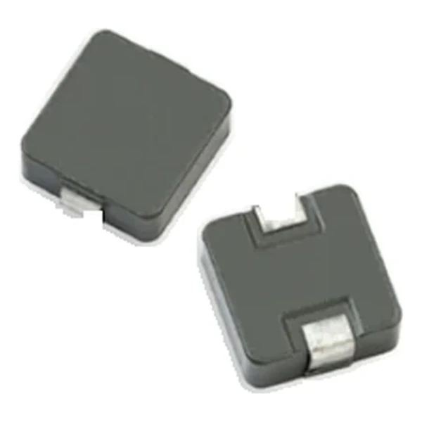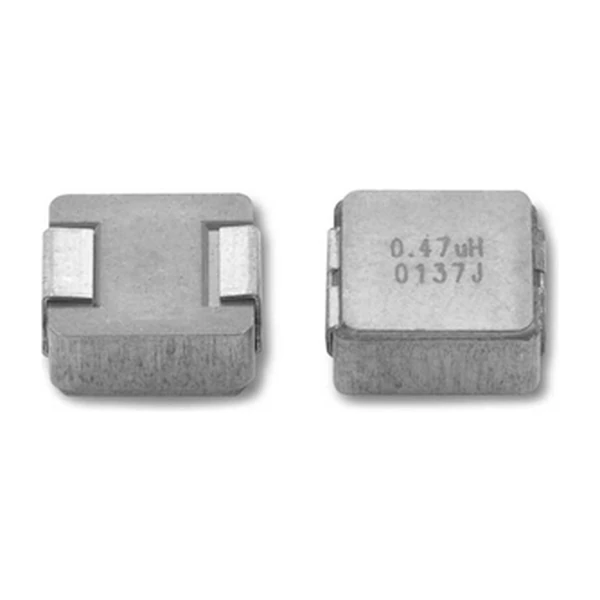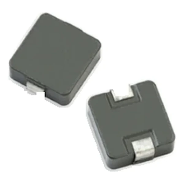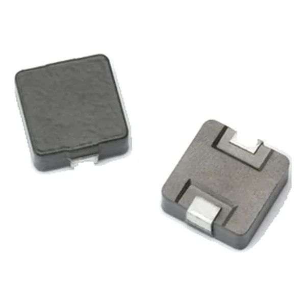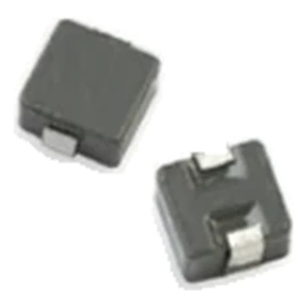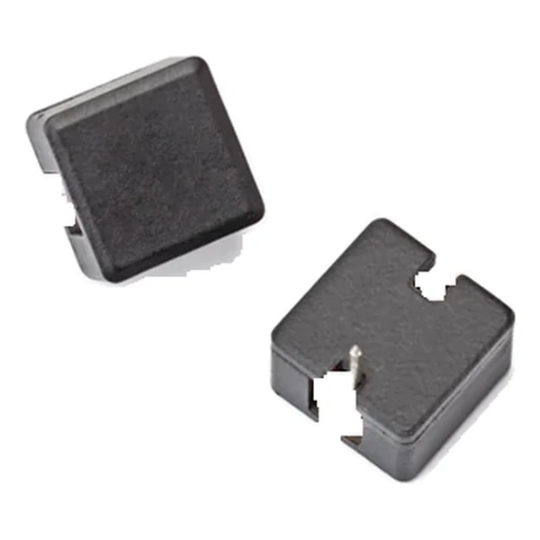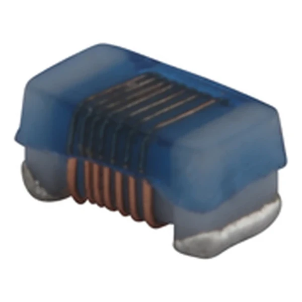
Eaton WCLA1005V1-9R0-R 9 nH Chip Inductor, Q 25
- Product Details
- Download
Eaton WCLA1005V1-9R0-R 9 nH Chip Inductor, Q 25
Electrical Specifications
| Parameter | Value |
|---|---|
| Orderable part number | WCLA1005V1-9R0-R |
| OCL | 9 nH ±5% |
| Q minimum @ test frequency | 25 @ 250 MHz |
| SRF minimum | 4160 MHz |
| DCR maximum @ +25 °C | 100 mOhm |
| Rated current (20 °C rise) | 680 mA |
| OCL test frequency | 250 MHz |
| OCL test voltage | 500 mV |
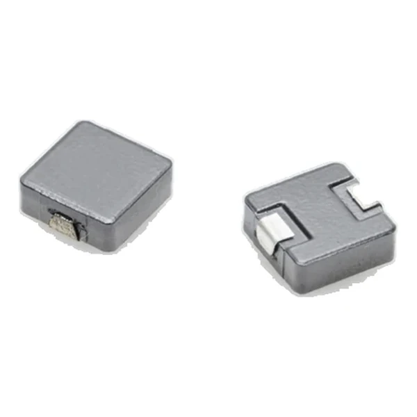
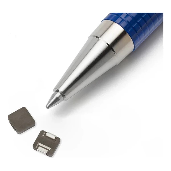
| Package | 1.19 x 0.66 mm, 0.60 mm high |
| Mounting | Surface mount |
| Operating temperature | -40 °C to +125 °C |
| Qualification | AEC-Q200 |
| RoHS | Compliant, -R suffix |
| Data sheet | Eaton Technical Data 10981 |
Dimensions and Pad Layout

Drawing reproduced from Eaton Technical Data 10981: outline views
with rated mm dimensions, pad layout and marking.
How to Read These Ratings
The value is small and the current is modest, so the design question is not saturation but Q and self-resonance. Q is quoted at one test frequency and SRF is the point where the winding capacitance takes over; both have to be read against the band the part actually works in.
At the 680 mA rating the winding drops about 68 mV and dissipates 46.2 mW. Both are small enough to ignore in a bias network but not in a high-Q filter.
Q of 25 at 250 MHz with self-resonance at 4160 MHz puts the useful band comfortably below the point where the winding capacitance takes over.
Within the WCLA1005V1 family this is value 23 of 52, in a range from 1 to 120 nH.
Positioning in the Range
The WCL and WCLA families run from 1.0 nH in a 1.19 x 0.66 mm body to 560 uH in 3.5 x 2.9 mm, with Q quoted at a stated test frequency for every row.
- The rated current is a 20 °C rise figure, not a saturation limit. In a DC bias application check the inductance at the actual bias before sizing the filter.
- Typical applications: adas; infotainment; wireless communications; wifi, bluetooth, satellite; antenna tuning.
- Design note: read Q and SRF at the frequency the part works at, not at the test frequency printed in the table.
Frequently Asked Questions
How is Q specified?
At one test frequency, given in the table. Q falls away either side of that point, so a part quoted at 25 MHz tells you little about behaviour at 900 MHz.
What does the rated current mean here?
It is the current that produces a 20 °C self-temperature rise, not a saturation limit. On a ceramic-core part there is no saturation to speak of, so the thermal figure is the only limit.
What does the rated current mean here?
It is the current that produces a 20 °C self-temperature rise, not a saturation limit. On a ceramic-core part there is no saturation to speak of, so the thermal figure is the only limit.
Shenzhen Gaorunxin Technology Co., Ltd
Online message
Shenzhen Gaorunxin Technology Co., Ltd