Welcome to our company!



MP1918 3.7-5.5V Half-Bridge GaN/MOSFET Driver QFN-14
Share
pMPS MP1918 — Half-Bridge GaN/MOSFET Driver, 3.7-5.5V input, QFN-14./p
- Product Details
- Download
MP1918 3.7-5.5V Half-Bridge GaN/MOSFET Driver QFN-14
The MPS MP1918 is a Half-Bridge GaN/MOSFET Driver. It operates from a 3.7 V to 5.5 V input. It is supplied in a QFN-14 package.
The MP1918 is a 100V half-bridge driver designed to drive enhancement mode Gallium Nitride (GaN) FETs or N-channel MOSFETs with a low gate threshold voltage in a half- bridge or synchronous application.
Key Specifications
| Part Number | MP1918 |
| Function | Half-Bridge GaN/MOSFET Driver |
| Input Voltage | 3.7 V to 5.5 V |
| Interface | PWM |
| Package | QFN-14 |
| Ordering Codes | MP1918 |
Features
- Independent High-Side (HS) and Low-Side (LS) TTL Logic Inputs
- HS Floating Bias Voltage Rail Operates Up to 100VDC
- Separate Gate Outputs for Adjustable Turn- On and Turn-Off Capabilities
- Internal Bootstrap Switch Supply Voltage Clamping
- 3.7V to 5.5V VCC Voltage (VCC) Range
- 0.27Ω/1.2Ω Pull-Down/Pull-Up Resistance
- Fast Propagation Times
- Excellent Propagation Delay Matching (Typically 1.5ns)
- Available in a QFN-14 (3mmx3mm) Package with Wettable Flanks
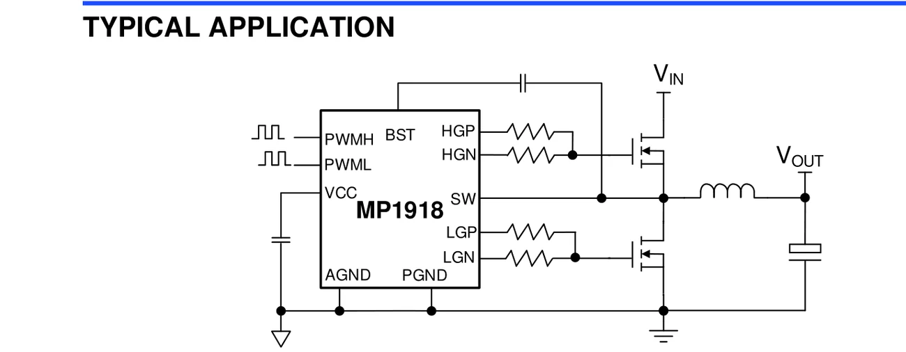
Typical Application Circuit
Applications
- Half-Bridge and Full-Bridge Converters
- Audio Class-D Amplifiers
- Synchronous Buck Converters
Design Notes
- The current-limit threshold must stay inside the SOA of the pass device at the applied voltage, including startup inrush.
- Hot-swap inrush control is set by the slew rate on the gate or the dV/dt capacitor — too fast trips the upstream supply.
- Reverse-current blocking behaviour differs between ideal-diode and load-switch topologies; pick the one that matches the fault you are protecting against.
- Route the fault flag to a pin the firmware actually polls; a latch-off protection with no report looks like a dead board in the field.
Common Questions
What input voltage does the MP1918 support?
3.7 V to 5.5 V.
Which package and ordering codes apply to the MP1918?
QFN-14; order codes include MP1918.
What are the defining features of the MP1918?
Independent High-Side (HS) and Low-Side (LS) TTL Logic Inputs HS Floating Bias Voltage Rail Operates Up to 100VDC
Shenzhen Gaorunxin Technology Co., Ltd
Online message
Shenzhen Gaorunxin Technology Co., Ltd